
User's Manual
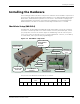
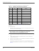
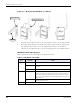
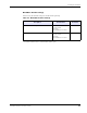
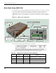
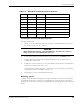
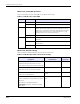
Table Of Contents
- MeshScape™ RK-5424-5 Reference Kit for 2.4 GHz MeshScape Systems User's Guide
- Contents
- About This Guide
- 1: Introduction
- 2: Installing the MeshScape System
- 3: Running MeshScape Network Monitor
- MeshScape Network Monitor Overview
- Configuring a Node’s Operation
- Labeling an End Node or Mesh Node
- Configuring Persistence Attributes
- Selecting a Com Port on the Host PC
- Configuring Serial and ADC Data Formats
- Turning Event Tracking On/Off
- Broadcasting Data to All Nodes.
- Creating an Event Log File
- Viewing the Contents of an Event Log File
- Viewing MeshScape Statistics
- 4: Using the MeshScape API
- A: Running the Demo Application
- B: Using MeshScape Programmer
- Glossary
- Index

RK-5424-5 Reference Kit User’s Guide 2-9
Installing the Hardware
Installing the antenna and applying power
To install a Mesh Node:
1. Attach one of the four supplied 1/2-wave antennas to the RP-SMA antenna connector.
The antenna screws onto the connector.
2. Ensure that the Mesh Node External Power Source Switch is in the DC Ext position.
3. Plug the supplied AC adapter into the MeshGate power connector and then into a
110/220 VAC power source.
4. Remove the connector panel access cover and slide the on/off switch to the ON position.
Replace the connector panel access cover.
The Mesh Node is ready to operate as a router device (see note below). For information
on the behavior of the status LEDs, see
Table 2-5.
5. Repeat Steps 1 to 4 for each Mesh Node in the kit.
Mounting options
You may operate the mesh node while it is resting on a desktop or mounted to a wall. When
mounting the mesh node to a wall, we recommend that you secure the mesh node in place
using two #6 screws and screw anchors (not supplied) of the appropriate type for the mounting
surface.
5 DIO4 I/O Not used.
6 AD0 Input Analog Input 0
7 AD1 Input Analog Input 1
8 AD2 Input Analog Input 2
9 AD3 Input Analog Input 3
10 3.3V Output Power 3.3V output power
11 GND Power Digital ground
12 + Power Input power (4.5V to 30V)
Caution
When attaching the antenna, only hand-tighten the antenna to the connector.
Using excessive force may damage the connector.
Table 2-4. Mesh Node terminal block pin assignments
Pin Label Input/Output Function