
User's Manual
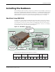
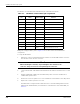
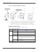
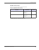
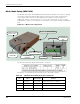
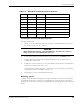
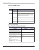
Table Of Contents
- MeshScape™ RK-5424-5 Reference Kit for 2.4 GHz MeshScape Systems User's Guide
- Contents
- About This Guide
- 1: Introduction
- 2: Installing the MeshScape System
- 3: Running MeshScape Network Monitor
- MeshScape Network Monitor Overview
- Configuring a Node’s Operation
- Labeling an End Node or Mesh Node
- Configuring Persistence Attributes
- Selecting a Com Port on the Host PC
- Configuring Serial and ADC Data Formats
- Turning Event Tracking On/Off
- Broadcasting Data to All Nodes.
- Creating an Event Log File
- Viewing the Contents of an Event Log File
- Viewing MeshScape Statistics
- 4: Using the MeshScape API
- A: Running the Demo Application
- B: Using MeshScape Programmer
- Glossary
- Index

2-8 Millennial Net
Installing the MeshScape System
Mesh Node Setup (MN-5424)
The Mesh Nodes, model number MN-5424 (label with model number on bottom), are shipped
enclosed in cases that provide: RP-SMA antenna connector, three-position external power
source switch, and a connector for the supplied power adapter as shown in
Figure 2-7.
Additionally, a lift-off connector panel access cover on the case provides access to a 12-pin
terminal block connector, a reset button, an on/off switch, and a six-pin external programming
port.
Figure 2-7. Mesh node components
The pin-out for the Mesh Node terminal block is as follows:
The function of each Mesh Node terminal block pin is described as follows:
Table 2-4. Mesh Node terminal block pin assignments
Pin Label Input/Output Function
1 DIO0/RxD I/O or Output Digital Input/Output 0 or UART RX
2 DIO1/TxD I/O or Input Digital Input/Output 1 or UART TX
3 DIO2/RTS I/O or Input Digital Input/Output 2or UART RTS (in)
4 DIO3/CTS I/O or Output Digital Input/Output 3 or UART CTS (out)
Connector Panel
Access Cover
RP-SMA Antenna Connector
External
Power Source Switch
External
Programming
Port
Power LED
RF Activity LED
Status LED
Power Adapter
Connector
Reset Button
On/Off Switch
Terminal Block