
User Manual
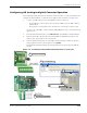
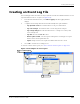
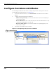
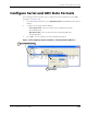
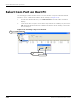
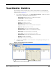
Table Of Contents
- About This Guide
- Introduction
- Kit Installation
- iB-5209 Network Monitor Operations
- iB-5209 Network Monitor Overview
- Setting Thread Priority
- Configuring a Node’s Operation
- Using Watch function to display current I/O information
- Configuring Sample Interval of Single Node
- Configuring Sample Interval of all Network Nodes
- Configuring Digital I/O Operation
- Configuring UART Operation
- Configuring AD (analog-to-digital) Converter Operation
- Configuring RS-232 Operation (RT-5209 only)
- Configuring RS-485 Operation (RT-5209 only)
- Labeling i-Bean Endpoint or i-Bean Router
- Creating an Event Log File
- Configure Persistence Attributes
- Configure Serial and ADC Data Formats
- Select Com Port on Host PC
- View Monitor Statistics
- View Contents of Event Log File
- Enable Multiple Capture
- API Functions
- Sample Application

EK-5209-5 Evaluation Kit User’s Guide 3-17
Configuring a Node’s Operation
Configuring AD (analog-to-digital) Converter Operation
The following procedure describes the steps that need to be taken to set up the hardware and
configure an i-Bean Endpoint or i-Bean Router for AD Converter operation (see Figure 3-8):
1. Connect 0–3 VDC signals to the following A/D Converter connectors:
– i-Bean Endpoint: Connect signal source ground to GND_CPU of the A/D Converter
terminal block.
– i-Bean Router: Connect signal source ground to Pin 1 (Ground) of connector SL4.
Use any or all of the A/D Converter channels (AD0–AD3/Pins 2–5) for connecting analog
signal sources.
2. From iB-5209 Network Monitor, select Edit>Devices. The Edit Device window displays.
3. Enter the device ID of the desired node and click Set. The Edit Device window is now
ready to make any changes to the selected node.
4. From the AD Converter panel, select the AD Converter channels to which the external
analog signals have been connected, then select Update.
iB-5209 Network Monitor displays the analog information for the node in the ADC (V)
column.
Figure 3-8. Configuring i-Bean Endpoint/i-Bean Router for analog I/O
Connect 0–3 V signals
1
Select node
3
Select analog channels,
4
Select Edit>Devices
2
then Update
Connect 0–3 V signals
1