
User Manual
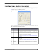
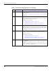
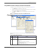
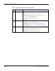
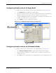
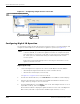
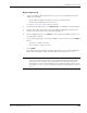
Table Of Contents
- About This Guide
- Introduction
- Kit Installation
- iB-5209 Network Monitor Operations
- iB-5209 Network Monitor Overview
- Setting Thread Priority
- Configuring a Node’s Operation
- Using Watch function to display current I/O information
- Configuring Sample Interval of Single Node
- Configuring Sample Interval of all Network Nodes
- Configuring Digital I/O Operation
- Configuring UART Operation
- Configuring AD (analog-to-digital) Converter Operation
- Configuring RS-232 Operation (RT-5209 only)
- Configuring RS-485 Operation (RT-5209 only)
- Labeling i-Bean Endpoint or i-Bean Router
- Creating an Event Log File
- Configure Persistence Attributes
- Configure Serial and ADC Data Formats
- Select Com Port on Host PC
- View Monitor Statistics
- View Contents of Event Log File
- Enable Multiple Capture
- API Functions
- Sample Application

3-10 EK-5209-5 Evaluation Kit User’s Guide
iB-5209 Network Monitor Operations
C DIO Channels This panel displays the following information for each digital channel
(0–3):
• State: Current input/output state of the channel
• Desired: Desired input/output state of channel, which can be
changed using the Edit>Devices option.
• Value: I/O values of the channel (1 or 0).
• Desired: Desired I/O value of channel.
D Sampling Interval This panel displays the following sampling interval information:
• Current: Currently configured setting.
• Desired: Desired setting, which can be changed using the
Edit>i-Bean option (see ’Configuring Sample Interval of Single
Node’ on page 3-11).
E Serial Data This panel displays the following serial data information of data received
from the node (In) or transmitted to the node (Out):
• State: State of the serial data function (1 or 0)
• Length: Length of string received/transmitted.
Table 3-2. Watch window functions (continued)
Item Description Function