
User Manual

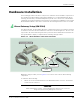
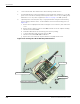
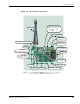
Table Of Contents
- About This Guide
- Introduction
- Kit Installation
- iB-5209 Network Monitor Operations
- iB-5209 Network Monitor Overview
- Setting Thread Priority
- Configuring a Node’s Operation
- Using Watch function to display current I/O information
- Configuring Sample Interval of Single Node
- Configuring Sample Interval of all Network Nodes
- Configuring Digital I/O Operation
- Configuring UART Operation
- Configuring AD (analog-to-digital) Converter Operation
- Configuring RS-232 Operation (RT-5209 only)
- Configuring RS-485 Operation (RT-5209 only)
- Labeling i-Bean Endpoint or i-Bean Router
- Creating an Event Log File
- Configure Persistence Attributes
- Configure Serial and ADC Data Formats
- Select Com Port on Host PC
- View Monitor Statistics
- View Contents of Event Log File
- Enable Multiple Capture
- API Functions
- Sample Application

EK-5209-5 Evaluation Kit User’s Guide 2-7
Hardware Installation
Figure 2-3. i-Bean Router components
REV-SMA Antenna Connector
(SL1) Power Connector
Battery or AC Adapter
Pin 1(right): GND
Pin 2(left): +
Notes: 1. Callouts for SL1–8 and RS-485 point to pin 1 of each connector
2. Connectors labeled as N/A are for Millennial Net use only.
Power Jack (N/A)
Power Switch
ON/OFF
RS-232 Port
LED 1 (red)
Signal Indicator
LED 2 (green)
Power Indicator
Antenna
RS-485 Connector
(SL5) UART Connector
(SL3) DIO
Digital I/O Connector
(SL8) N/A
(SL7) N/A
(SL4) ADC
A/D Converter Connector
(SL2) N/A
(JP1) Jumper
Pins 2 & 3 jumped
(SL6) N/A