
User Manual

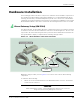
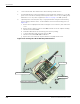
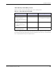
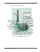
Table Of Contents
- About This Guide
- Introduction
- Kit Installation
- iB-5209 Network Monitor Operations
- iB-5209 Network Monitor Overview
- Setting Thread Priority
- Configuring a Node’s Operation
- Using Watch function to display current I/O information
- Configuring Sample Interval of Single Node
- Configuring Sample Interval of all Network Nodes
- Configuring Digital I/O Operation
- Configuring UART Operation
- Configuring AD (analog-to-digital) Converter Operation
- Configuring RS-232 Operation (RT-5209 only)
- Configuring RS-485 Operation (RT-5209 only)
- Labeling i-Bean Endpoint or i-Bean Router
- Creating an Event Log File
- Configure Persistence Attributes
- Configure Serial and ADC Data Formats
- Select Com Port on Host PC
- View Monitor Statistics
- View Contents of Event Log File
- Enable Multiple Capture
- API Functions
- Sample Application

2-6 EK-5209-5 Evaluation Kit User’s Guide
Kit Installation
i-Bean Router Setup (RT-5209)
The i-Bean Routers, model number RT-5209, are shipped without cases to provide full access to
the various I/O connectors. (While the i-Bean Gateway has similar connectors, they are only
functional on the i-Bean Router.) Refer to Figure 2-3 on page 2-7 for locations of the various
i-Bean Router switches and connectors described in the following procedure.
To install an i-Bean Router:
1. Attach one of the included antennas to the REV-SMA antenna connector. The antenna
screws onto the connector.
2. Turn the Power Switch OFF.
3. Connect one of the following power sources supplied with the kit:
– Regulated AC Adapter (recommended): Plug the regulated AC adapter into keyed
connector SL1 and a 110 VAC power source.
– Batteries: To install batteries and connect the battery pack:
a. Install two AA batteries into the battery pack (observe polarity).
b. Connect the battery pack to keyed connector SL1.
4. Turn the Power Switch ON. LED 2 (green) illuminates, indicating power is applied to the
device (see Table 2-2 on page 8 for LED operation).
5. Repeat Steps 1–4 for each i-Bean Router in the kit.
Caution
A jumper is factory-installed on JP1 that connects pins 2 and 3 together. Do not remove or
change the position of this jumper as it will cause the device to malfunction.
Caution
When attaching the antenna, only hand-tighten the antenna to the connector.
Using excessive force may damage the connector.
Note:
C
Configuring and connecting an i-Bean Endpoint or i-Bean Router to external devices
via their digital or analog I/O connectors is discussed in Chapter 3, “iB-5209
Network Monitor Operations”.