
User Manual
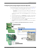
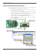
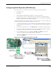
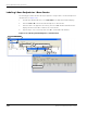
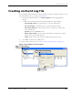
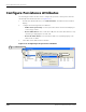
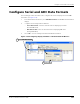
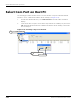
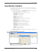
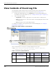
Table Of Contents
- About This Guide
- Introduction
- Kit Installation
- iB-5209 Network Monitor Operations
- iB-5209 Network Monitor Overview
- Setting Thread Priority
- Configuring a Node’s Operation
- Using Watch function to display current I/O information
- Configuring Sample Interval of Single Node
- Configuring Sample Interval of all Network Nodes
- Configuring Digital I/O Operation
- Configuring UART Operation
- Configuring AD (analog-to-digital) Converter Operation
- Configuring RS-232 Operation (RT-5209 only)
- Configuring RS-485 Operation (RT-5209 only)
- Labeling i-Bean Endpoint or i-Bean Router
- Creating an Event Log File
- Configure Persistence Attributes
- Configure Serial and ADC Data Formats
- Select Com Port on Host PC
- View Monitor Statistics
- View Contents of Event Log File
- Enable Multiple Capture
- API Functions
- Sample Application

EK-5209-5 Evaluation Kit User’s Guide 3-19
Configuring a Node’s Operation
Configuring RS-485 Operation (RT-5209 only)
The RS-485 interface of the i-Bean Router operates using the following parameters:
• Half-duplex mode
• 9600 baud
• Transmitting data: Maximum byte length for one request is 80 bytes
• Receiving data: Reception is terminated by the router when the maximum input byte
length is reached or there is no input for more than 20 ms. Once the input is terminated,
the data is transferred to iB-5209 Network Monitor.
The following procedure describes the steps that need to be taken to set up the hardware and
configure an i-Bean Router for RS-485 operation (see Figure 3-10):
1. Connect the network device to the standard 2-position RS-485 terminal block using the
pinout information provided in Figure 3-10. The terminal block will accept 26 AWG to 16
AWG wire.
2. From iB-5209 Network Monitor, select Edit>Devices. The Edit Device window displays.
3. Enter the device ID of the desired i-Bean Router and click Set. The Edit Device window is
now ready to make any changes to the selected i-Bean Router.
4. From the Digital I/O panel, select Serial Data: RS-485, then Update. The RS-485
connector is ready for operation (digital function is disabled).
5. (optional) To send serial data to the i-Bean Router, enter the data in the Serial Data panel,
then select Send Data.
Figure 3-10. Configuring i-Bean Router for RS-485
Connect signals
1
Select node
3
Select Edit>Devices
2
(optional) Enter serial data,
5
then select Send Data
Select RS-485,
4
then select Update