
User Manual

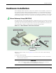
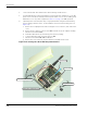
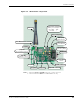
Table Of Contents
- About This Guide
- Introduction
- Kit Installation
- iB-5209 Network Monitor Operations
- iB-5209 Network Monitor Overview
- Setting Thread Priority
- Configuring a Node’s Operation
- Using Watch function to display current I/O information
- Configuring Sample Interval of Single Node
- Configuring Sample Interval of all Network Nodes
- Configuring Digital I/O Operation
- Configuring UART Operation
- Configuring AD (analog-to-digital) Converter Operation
- Configuring RS-232 Operation (RT-5209 only)
- Configuring RS-485 Operation (RT-5209 only)
- Labeling i-Bean Endpoint or i-Bean Router
- Creating an Event Log File
- Configure Persistence Attributes
- Configure Serial and ADC Data Formats
- Select Com Port on Host PC
- View Monitor Statistics
- View Contents of Event Log File
- Enable Multiple Capture
- API Functions
- Sample Application

EK-5209-5 Evaluation Kit User’s Guide 2-3
Hardware Installation
Hardware Installation
The following procedures describe in order, how to install the various hardware components of
the evaluation kit. When initially setting up the hardware, it is recommended that the i-Bean
Gateway, i-Bean Routers, and i-Bean Endpoints be placed close to the host PC. This will make
verifying proper network installation and operation easier when first establishing a session with
iB-5209 Network Monitor. The devices can then be moved away from the host PC as needed.
i-Bean Gateway Setup (GW-5209)
The i-Bean Gateway, model number GW-5209, is shipped enclosed in a case that has openings
for instant access to the antenna and RS-232 connectors as shown in Figure 2-1. The case cover
only needs to be removed should you decide to power the device with batteries instead of the
factory-installed AC adapter, as explained in the following setup procedure.
Figure 2-1. i-Bean Gateway components (external)
During the setup procedure, refer to Figure 2-1 for location of the various i-Bean Gateway
components.
To install the i-Bean Gateway:
1. Attach one of the included antennas to the REV-SMA antenna connector. The antenna
screws onto the connector.
Caution
When attaching the antenna, only hand-tighten the antenna to the connector.
Using excessive force may damage the connector.
REV-SMA Antenna Connector
Regulated AC Adapter
Antenna
LED 2 Window
(Green)
RS-232 Port
LED 1 Window
(Red)