IoT E-ink Display Featuring LoRaWAN® DS3604 User Guide
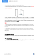
Safety Precautions Milesight will not shoulder responsibility for any loss or damage resulting from not following the instructions of this operating guide. The device must not be modified in any way. In order to protect the security of the device, please change device the password when first configuration. The default password is 123456. Do not place the device close to objects with naked flames. Do not place the device where the temperature is below/above the operating range.
Contents 1. Product Introduction ......................................................................................................................... 4 1.1 Overview ...................................................................................................................................4 1.2 Features ................................................................................................................................... 4 2. Hardware Introduction .....................................
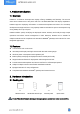
1. Product Introduction 1.1 Overview DS3604 is a reflective electrophoretic display offering readability and flexibility. The 4.2-inch active area contains 400 x 300 pixels and has 1-bit Black/White/Red full display capabilities. DS3604 supports displaying information in customized templates and allows for secondary development through interfaces. Long-capacity batteries and ultra-low power consumption bring a long battery life of up to 5 years.
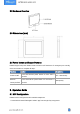
2.2 Hardware Overview 2.3 Dimensions (mm) 2.4 Power button and Buzzer Patterns DS3604 equips with power button inside to switch on/off the device for emergency use. Usually, users can use NFC to complete all steps. Function Power On/Off Action Press and hold the power button for more than 3 seconds. Reset to Press and hold the power button for more than 10 Factory Default seconds. Buzz Status Off → Buzz slowly Buzz quickly 3. Operation Guide 3.
2. Enable NFC on the smartphone and open Milesight ToolBox. 3. Attach the smartphone with NFC area to the device to read device information when the screen is not refreshing. 4. Basic information and settings of the device will be shown on ToolBox if it’s recognized successfully. You can read and configure the device by tapping the Read/Write button on the App. In order to protect the security of devices, password validation is required when first configuration. The default password is 123456.
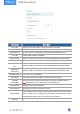
Parameters Device EUI App EUI Application Port Join Type Description Unique ID of the device which can also be found on the label. Default App EUI is 24E124C0002A0001. The port is used for sending and receiving data, the default port is 85. OTAA and ABP modes are available. Application Key Appkey for OTAA mode, default is 5572404C696E6B4C6F52613230313823. Device Address DevAddr for ABP mode, default is the 5th to 12th digits of SN.
If frequency is one of CN470/AU915/US915, enter the index of the channel that you want to enable and make them separated by commas. Examples: 1, 40: Enabling Channel 1 and Channel 40 1-40: Enabling Channel 1 to Channel 40 1-40, 60: Enabling Channel 1 to Channel 40 and Channel 60 All: Enabling all channels Null: Indicates that all channels are disabled Spread Factor Confirmed Mode If ADR is disabled, the device will send data via this spread factor.
ADR Mode Allow network server to adjust datarate of the device. Tx Power Transmit power of the device. Note: 1) Please contact sales representative for device EUI list if there are many units. 2) Please contact sales representative if you need random App keys before purchase. 3) Select OTAA mode if you use Milesight IoT Cloud to manage devices. 4) Only OTAA mode supports rejoin mode. 5) For -868M model, the default frequency is EU868; for -915M model, the default frequency is AU915. 3.2.
Parameters Multicast Address Description Unique 8-digit address to distinguish different multicast groups. 32-digit key. Default values: Multicast Group 1: 5572404C696E6B4C6F52613230313823 McNetSkey Multicast Group 2: 5572404C696E6B4C6F52613230313824 Multicast Group 3: 5572404C696E6B4C6F52613230313825 Multicast Group 4: 5572404C696E6B4C6F52613230313826 32-digit key.
4. Go to Network Server > Packets, select the multicast group and fill in the downlink command, click Send. The network server will broadcast the command to devices that belong to this multicast group. Note: ensure all devices’ application ports are the same.
3.3 General Settings Go to Device > Setting > General Settings of ToolBox App to change the reporting interval, etc. Parameters Reporting Interval Buzzer Description The interval of sending battery level and display template option to network server. Range: 1-1080 mins, default: 1080 min When buzzer is enabled, it will response when you press the screen button or the device receives the downlink command to refresh the screen.
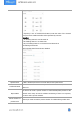
Icon Description Text Double click to edit the text content or single click to adjust the properties (color, background, size, font-family, font-weight, align) or drag to move this module. One template can add 10 text modules at most and every text can include 63 characters at most. Image Double click to import an image or single click to adjust the properties or drag to move this module. One template can only add one image and the resolution must be 400*300.
Background Electricity Disconnect Import an image as background, the image resolution should be 400*300. Two templates can only add one background. When battery level is lower than 10%, this module will display. The properties of this module are non-editable and you can change the location by dragging it or modify the X&Y value. When the device fails to join the network, this module will display.
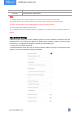
3. Click Write to save this template and write it to the screen. 4. Click Export Config to save current template to your smartphone and you can import this template to another device by clicking Import Template. 3.5 Maintenance 3.5.1 Upgrade 1. Download firmware from Milesight website to your smartphone. 2. Open ToolBox App and click Browse to import firmware and upgrade the device. Note: 1) Operation on ToolBox is not supported during the upgrade.
Note: Slide the template item to the left to edit or delete the template. Click the template to edit the configurations. 3.5.3 Reboot and Reset Via Hardware: Hold on the power button inside the device for 3s to reboot, 10s to reset. Via ToolBox App: Go to Device > Maintenance to tap Reset, then attach smartphone with NFC area to the device to complete reboot or reset.
4. Installation DS3604 can be placed on the desktop directly. If it needs to be fixed, please try below installation methods. Fixed by 3M Tapes: Paste 3M tape to the back of the device, then tear the other side and place it on a flat surface. Please note the screen direction when installing. Fixed by Screws: 1. Release the screw on the bottom of device and remove the back cover, mark the installing holes to the wall according to the holes on the back cover. 2.
Installation Note: If the installation location is a metal surface or includes metal materials, please leave the upper part of device 3 to 4 cm away from the surface to avoid the signal problem. 5. Device Payload All data are based on the following format(HEX), the Data field should follow little -endian: Channel1 Type1 Data1 Channel2 Type2 Data2 Channel 3 ... 1 Byte 1 Byte N Bytes 1 Byte 1 Byte M Bytes 1 Byte ... For decoder examples you can find them at https://github.
Example: ff0bff ff0101 ff166601c42255890001 ff090100 ff0a0101 ff0f01 Channel Type Value Channel Type Value ff 0b (Power On) ff (Reserved) ff 01 (Protocol Version) 01 (V1) Channel Type Value Channel Type Value ff 16(Device SN) 6601c422558 90001 ff 09 (Hardware version) 0100 (V1.0) Channel Type Value Channel Type Value ff 0a (Software version) 0101 (V1.1) ff 0f (Device Type) 01(Class B) 5.
01: Enable 01: Buzz twice 3d (Action) 02: Screen refresh 00: Disable 3e (Buzzer) 01: Enable 00: template 1 73 (Display Template) 01: template 2 1 Byte, Bit 4~7: multicast group 1 to 4 change status, 0 = not allow control, 1 = allow control. Bit 0~3: multicast group 1 to 4 control status, 82 (Multicast group) 0 for disable, 1 for enable. Note: after disabling or enabling, the device will re-join the network. Example: 1. Set reporting interval as 20 minutes.
Command format: Channel Type Description ID (1B)+Content Size(1B)+Content (Mutable) fb 01 (Text/QR Code Content Update) ID: Bit 7-bit 6: 00=template 1, 01=template 2 Bit5-Bit 0: module ID Content: UTF-8 format content Reply format: Channel Type Description ID(1B)+Code(1B) ID: Bit 7-bit 6: 00=template 1, 01=template 2 Bit5-Bit 0: module ID fa 01 (Text/QR Code Content Code description: Update) 00: content update success 01: no this template 02: no this module 03: invalid content length 04: this m
Reply: fa010000 fe3d02 Channel Type Value Channel Type Value fa 01 (Text content update) 00: template 1, module 1 00: update success fe 3d(Screen Refresh) 02 -END- 22