
Owner's Manual
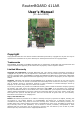

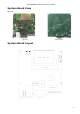
Table Of Contents
RouterBOARD 411AR Series User's Manual
Powering
Power options:
● J801 power jack:
10..28V DC (supports overvoltage protection)
● Power over Ethernet (PoE) on the J602 LAN1 Ethernet port:
10..28V DC (18..28 V suggested) non-standard PoE powering support
The board has a direct-input power jack J801 (5.5mm outside and 2mm inside diameter, female, pin
positive plug) and can as well be powered with PoE. All power inputs are always active, but only one should
be used at the same time.
RouterBOARD 411AR is equipped with a reliable 14W onboard power supply with overvoltage protection.
9..28 V DC input voltages are accepted, but when powered over long cables, it is suggested to use at least
18V. The system is tested with 24V solar/wind/RV systems with 27.6 charge voltage. Overvoltage protection
starts from about 28V (up to 100V), so the board will not be damaged if connected to a 48V or 60V power
line.
RouterBOARD 411AR series boards are compatible with non-standard (passive) Power over Ethernet
injectors (except power over datalines) and accept powering over up to 100m (330 ft) long Ethernet cable
connected to the Ethernet port (J602). The board does not work with IEEE802.3af compliant 48V power
injectors.
The maximum output of the power supply to the extension cards is normally at about 3.3A
Booting options
First, RouterBOOT loader is started. It displays some useful information on the onboard RS232C
asynchronous serial port, which is set to 115200bit/s, 8 data bits, 1 stop bit, no parity by default. The loader
may be configured to boot the system from the onboard NAND module or from Ethernet network. See the
respective section of this manual for how to configure booting sequence and other boot loader parameters.
Onboard NAND Storage Device
The RouterBOARD may be started from the onboard NAND storage chip. As there is no partition table on the
device, the boot loader assumes the first 4MiB form a YAFFS filesystem, and executes the file called “kernel”
stored in the root directory on that partition.
Booting from network
Network boot works similarly to PXE or EtherBoot protocol, and allows you to boot a RouterBOARD 411
series computer from an executable image stored on a TFTP server. It uses BOOTP or DHCP (configurable in
boot loader) protocol to get a valid IP address, and TFTP protocol to download an executable (ELF) kernel
image combined with the initial RAM disk (inserted as an ELF section) to boot from (the TFTP server's IP
address and the image name must be sent by the BOOTP/DHCP server).
To boot the RouterBOARD computer from Ethernet network you need the following:
● An ELF kernel image for the loader to boot from (you can embed the kernel parameters and initrd
image as ELF sections called kernparm and initrd respectively)
● A TFTP server which to download the image from
● A BOOTP/DHCP server (may be installed on the same machine as the TFTP server) to give an IP
address, TFTP server address and boot image name
See the RouterBOOT section on how to configure loader to boot from network.
Note that you must connect the RouterBOARD you want to boot, and the BOOTP/DHCP and TFTP servers to
the same broadcast domain (i.e., there must not be any routers between them).
RouterBOOT
The RouterBOOT firmware (also referred as “boot loader” here) provides minimal functionality to boot an
Operating System. It supports serial console via the onboard serial port at the boot time. The loader
supports booting from the onboard NAND device and from a network server (see the respective section for
details on this protocol).
6