
Owner's Manual
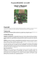
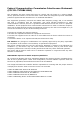

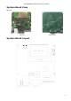
Table Of Contents

RouterBOARD 411AR Series User's Manual
power supply is more efficient).
See Connector Index for pinout of the standard cable required for PoE. All cables made to EIA/TIA 568A/B
cable specifications will work correctly with PoE. Note that this port supports automatic cross/straight cable
correction (Auto MDI/X), so you can use either straight or cross-over cable for connecting to other devices.
Onboard 802.11b/g wireless card
This RouterBOARD model has a built-in 802.11b/g wireless device based on the AR2417 Atheros chipset. Ufl
antenna connectors are located to the left of the card, as seen in the diagram of page 3.
RX sensitivity
802.11g
: –87 dBm @ 6Mbps to -69 dBm @ 54 Mbps
802.11b
: –92 dBm @ 1Mbps to –83 dBm @ 11 Mbps
TX power Up to 20 dBm
Modulations
802.11g
: OFDM,64QAM,16QAM,QPSK,BPSK
802.11b
: CCK,DSS,DQPSK, DBPSK
DB9 Serial Port
The RS232C standard male DB9 asynchronous serial port may be used for initial configuration, or for
attaching a modem or any other RS232 serial device. TxD (pin 3) of this port has -5V DC power when idle.
RTS and DTR signals are not connected. Note that the device does not fully implement the hardware
(RTS/CTS) flow control, so it is suggested to try to disable hardware flow control in the terminal emulation
program in case the serial console does not work as expected, and if it does not help, make a new cable
using the pinout given in the User's manual.
LEDs
Power LED
Power LED is on when the board is powered.
User LED
User LED may be programmed at user's option. It is lit by default when the board starts up, then it is turned
off when the bootloader runs kernel.
Status LEDs
Six LEDs (LD 501-506) are located to the right of the Serial port. Their functions are as follows:
• LED 1-5 are all user programmable
• LED 4 when not programmed shows Bootloader activity
• LED 5 when not programmed shows NAND activity
• LED 6 is used for Wireless activity (not active in current RouterOS versions)
User's Guide
Assembling the Hardware
First to use the board:
● Insert MiniPCI card and connect antenna wires, if needed;
● Install the board in a case;
● Connect other peripherals and cables.
5