
Installation Instructions
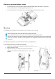
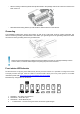
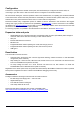
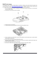
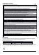
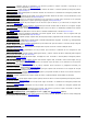
Table Of Contents
- Quickstart
- Powering
- MikroTik mobile app
- Removing upper and bottom covers
- Mounting
- Grounding
- Front status LED behavior
- Configuration
- Expansion slots and ports
- Reset button
- Accessories
- MiniPCIe slot usage
- Antenna usage
- Specifications
- Operating system support
- Safety Warnings
- Federal Communication Commission Interference Statement
- Innovation, Science and Economic Development Canada
MiniPCIe slot usage
This NetMetal version is without modem installed. To install the module you will need to remove the upper cover
and open bottom cover (see “Removing upper and bottom covers”). Installing a miniPCIe module should be done
by a qualified person, please follow safety precautions when handling electrical equipment:
1. Use a wrist grounding strap when unpacking and working with electrical components to avoid electrical
discharge (ESD) damage.
2. Removing four screws using the PH2 screwdriver.
3. Remove the top cover by lifting it.
4. Locate the miniPCIe slot on the PCB and remove two factory attached screws.
5. Attach provided a thick thermal pad to the card, and install the card into miniPCIe slot so that the thermal
pad is between PCB and card.
6. Secure card in place using previously removed two screws.
7. Attach the grey uFL connector to the MAIN antenna connector of the modem, attach the black cable to the
secondary (or AUX) connector.
8. Attach a thinner thermal pad to the top of the card.
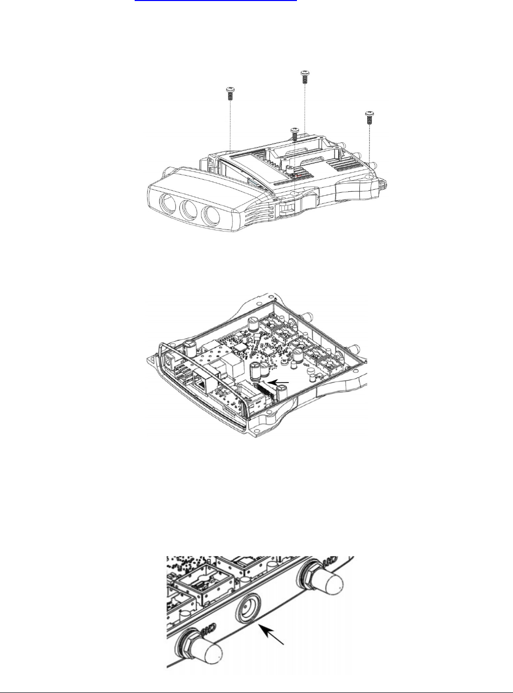
9. Drill a hole for cables using 6.5 mm drill to provide an opening for card antenna cables.
See mikrotik.com/products for the latest version of this document. Page 5, Document #53381 Modified on: 30.JAN.2020