
Installation Instructions
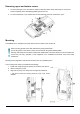
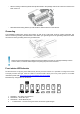
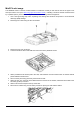
Table Of Contents
- Quickstart
- Powering
- MikroTik mobile app
- Removing upper and bottom covers
- Mounting
- Grounding
- Front status LED behavior
- Configuration
- Expansion slots and ports
- Reset button
- Accessories
- MiniPCIe slot usage
- Antenna usage
- Specifications
- Operating system support
- Safety Warnings
- Federal Communication Commission Interference Statement
- Innovation, Science and Economic Development Canada

Configuration
The device is configured as a wireless access point, with the Ethernet port configured as a DHCP client, for
connecting to your ISP router or switch. A DHCP server is configured on the wireless interface.
We recommend clicking the “Check for updates” button in the QuickSet menu, as updating your RouterOS software
to the latest version ensures the best performance and stability. For wireless models, please make sure you have
selected the country where the device will be used, to conform with local regulations.
RouterOS includes many configuration options in addition to what is described in this document. We suggest
starting here to get yourself accustomed to the possibilities: http://mt.lv/help. In case IP connection is not available,
the Winbox tool (http://mt.lv/winbox) can be used to connect to the MAC address of the device from the LAN side
(all access is blocked from the Internet port by default).
For recovery purposes, it is possible to boot the device for reinstallation, see section Reset button.
Expansion slots and ports
• Gigabit Ethernet port, supporting automatic cross/straight cable correction (Auto MDI/X). Either straight or
crossover cable can be used for connecting to other network devices.
• SFP port.
• External SMA antenna connectors.
• MiniPCIe slot.
• Integrated Wireless module operating at 2.4 GHz, 802.11b/g/n protocol.
• Integrated Wireless module operating at 5 GHz, 802.11a/n/ac protocol.
• USB type-A.
Reset button
The reset button has three functions:
• Hold this button during boot time until LED light starts flashing, release the button to reset RouterOS
configuration (total 5 seconds).
• Keep holding for 5 more seconds, LED turns solid, release now to turn on CAP mode. The device will now
look for a CAPsMAN server (total 10 seconds).
• Or Keep holding the button for 5 more seconds until LED turns off, then release it to make the
RouterBOARD look for Netinstall servers (total 15 seconds).
Regardless of the above option used, the system will load the backup RouterBOOT loader if the button is pressed
before power is applied to the device. Useful for RouterBOOT debugging and recovery.
Accessories
Package includes the following accessories that come with the device:
• EU Switching Power Supply 48 V ⎓ 0.95 A 45.6 W.
• Gigabit POE injector.
• K-27 DIN rail bracket mounting set.
• Hose clamp 40/60 w2 A2 9 mm.
Please visit wiki pages for MikroTik SFP module compatibility table:
https://wiki.mikrotik.com/wiki/MikroTik_SFP_module_compatibility_table
See mikrotik.com/products for the latest version of this document. Page 4, Document #53381 Modified on: 30.JAN.2020