
User's Manual
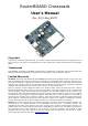
RouterBOARD Crossroads User's Manual
Hardware Guide
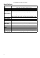
Memory and Storage Devices
Onboard Memory
The boards are equipped with one 32MB SDRAM memory chip.
Onboard NAND Storage Device
The boards are equipped with one 64MB NAND nonvolatile memory chip.
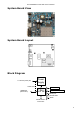
Input/Output Ports
LAN Port with PoE
This Fast Ethernet port is compatible with IEEE802.3af Power over Ethernet standard (includes power over
datalines) and passive PoE (non-standard). The board accepts non-standard voltage input in wide range:
from 11 to 60 V DC. The device has been tested with 802.3af PoE switches (Including Linksys, Rubitech) and
also passive PoE switches (see appendix for Ethernet cable specs).
A passive PoE power injector may be used to power the board with up to 100m (330 ft) long Ethernet cable.
It is suggested to use 48V DC power for power over long cables because of better efficiency (less power is
lost in the cable itself and the power supply is more efficient on higher voltage).
See Connector Index for pinout of the standard cable required for PoE. All cables made to EIA/TIA 568A/B
cable specifications will work correctly with PoE. Note that this port supports automatic cross/straight cable
correction (Auto MDI/X), so you can use either straight or cross-over cable for connecting to other network
devices.
WLAN Interface
This onboard IEEE802.11b/g wireless interface provides stable radio connection on the standard 2.4GHz
frequency range with 1W maximum output power (limited by regulatory settings). It has two antenna
connectors, of which only the main one (J5) is used by default, but the auxiliary connector (J4) can be
configured in the software as well.
DB9 Serial Port
The RS232C standard male DB9 asynchronous serial port may be used for initial configuration, or for
attaching a modem or any other RS232 serial device. TxD (pin 3) of this port has -5V DC power when idle.
DCD and DSR signals are not connected. This implementation may not be considered to support full
hardware flow-control so software flow-control (XON/XOFF) should be used.
LEDs
Power LED
A Blue LED is lit when the board is powered.
Wireless LEDs
A pairs of LEDs are connected to the onboard wireless interface according to standards.
User's Guide
Assembling the Hardware
First use of the board:
● In most cases you do not need to configure jumpers. JP2 PoE control is disabled by default, you may
want to enable it to comply with IEEE802.3af requirements. See Jumper Index for details.
● Install the board in a case.
● Connect other peripherals and cables
5