
User Manual
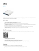
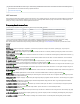
Table Of Contents

1.
2.
3.
First Ethernet port accepts passive Power over Ethernet accepts 11-57 V DC (compensate for the loss on cable, so more than 12 V
recommended).
The power consumption under maximum load can reach 5W.
Connecting to a PoE Adapter:
Connect the Ethernet cable from the device to the PoE+DATA port of the PoE adapter.
Connect an Ethernet cable from your local network (LAN) to the PoE adapter.
Connect the power cord to the adapter, and then plug the power cord into a power outlet.
Configuration
We recommend clicking the "Check for updates" button and updating your RouterOS software to the latest version to ensure the best performance and
stability. RouterOS includes many configuration options in addition to what is described in this document. We suggest visiting the RouterOS documentation
page to get yourself accustomed to the possibilities: .https://mt.lv/help
In case IP connection is not available, the Winbox tool ( ) can be used to connect to the MAC address of the device from the LAN side https://mt.lv/winbox
(all access is blocked from the internet port by default).
It is possible to boot the device from the network, for reinstalling RouterOS for recovery purposes. This can be done from the first Ethernet port. (See hAP
).ac#Buttons and jumpers
Extension slots and ports
Five individual 10/100/1000 Gigabit Ethernet ports, supporting automatic cross/straight cable correction (Auto MDI/X), so you can use either
straight or cross-over cables for connecting to other network devices.
Integrated Wireless 2.4 GHz and 5 GHz 802.11 a/b/g/n/ac, simultaneous triple-band radio with onboard antennas, max gain 2.5 dBi.
USB port.
SFP port.
The Ether 5 port supports PoE output for powering other RouterBOARD devices. It has an auto-detection feature, so you can connect Laptops and other
non-PoE devices without damaging them. The PoE on Ether5 outputs approximately 2 V below input voltage and supports up to 0.7 A (So provided 24 V
PSU will provide 22 V 0.7 A output to the Ether 5 PoE port).
Please visit wiki pages for MikroTik SFP module compatibility table: https://wiki.mikrotik.com/wiki/MikroTik_SFP_module_compatibility_table
Buttons and jumpers
The reset button has the following functions:
Hold this button during boot time until LED light starts flashing, release the button to reset RouterOS configuration (total 5 seconds).
Keep holding for 5 more seconds, LED turns solid, release now to turn on CAP mode. The device will now look for a CAPsMAN server (total 10
seconds).
Or Keep holding the button for 5 more seconds until LED turns off, then release it to make the RouterBOARD look for Netinstall servers (total 15
seconds).
Regardless of the above option used, the system will load the backup RouterBOOT loader if the button is pressed before power is applied to the device.
Useful for RouterBOOT debugging and recovery.
Specifications
For more information about this product, specifications, pictures, downloads and test results please visit our web page: https://mikrotik.com/product
/RB962UiGS-5HacT2HnT
Operating system support
The device supports RouterOS software version 6. The specific factory installed-version number is indicated in the RouterOS menu /system resource.
Other operating systems have not been tested.
Notice