
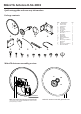
Quick Guide

H
V
FIG. 5
H
G
ØMAX = 70mm
FIG. 6
R Q
I
S
FIG. 7
Q N
D
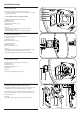
5. Install RF Cables
Remove the cover from MikroTik Radio and install the RF Cables [G].
Connect vercal polarizaon (arrow V) to CH0, horizontal polarizaon
(arrow H) to CH1 - see Fig. 5.
Insulate the RF Cable [G] ends which are connected to Antenna Feed [B]
by using: [H] Self-Bonding Tape Slice x 2pcs.
• Remove the plastic liner from both sides;
• Stretch the tape to 2/3 of its width;
• Apply half-lapped layers clockwise.
The RF Cable [G] ends which are connected to MikroTik Radio are insulated
by the cover.
Fit back the MikroTik Radio cover.
Important:
• RF Cables [G] connector ghtening torque must be approximately 0.5 Nm.
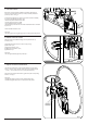
6. Aach Antenna to Pole
MikroTik Antenna D-5G-30D3 is design to fit the pole diameter up
to 70mm( 2.75”).
Aach MikroTik Antenna to pole as shown in Fig. 6 using:
[I] M8 U-Bolt x 2 pcs;
[S] M8 Fender Washer x 4 pcs;
[R] M8 Spring Lock Washer x 4 pcs;
[Q] M8 Nut x 4 pcs.
Important:
• Do not ghten M8 Nuts [Q] firmly unl step 7.
7. Adjust Azimuth and Elevaon
The Azimuth and Elevaon can be adjusted if M8 Nuts [Q] are slightly
loosen. In order to set the azimuth rotate the antenna around the pole
- see Fig. 7. The elevaon can be set by turning Back Plate [D].
Aer seng the azimuth and elevaon, ghten firmly the corresponding
fasteners - see Fig. 6.
Important:
• M6 Nut [N] ghtening torque must be approximately 5 Nm.
• M8 Nuts [Q] ghtening torque must be approximately 20 Nm.