
User manual


Robotics experiment with PIC microcontroller l 75
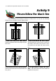
From the black line following behavior, you can apply to make the program to
control the Robo-PICA. See the Listing A9-1. The sequence of program operations are
1. Set the default value to interface A/D Converter module in PIC16F887
microcontroller.
2. Enable both DC motor driver circuits.
3. Get data from both sensors that connected at RA0 and RA1 port pins.
Load data to SENSOR0 (store data from RA0) and SENSOR1 (store data from RA1) variable
4. Compare the data read with the reference data. If SENSOR0 and SEN-
SOR1 data are more than the reference, control the robot to move forward.
5. If SENSOR0 and SENSOR1 data are less than the reference, control the
robot to move forward. This condition is the robot meets an intersection and decide to
move forward continue.
6. If SENSOR0 data is less than the reference only, the robot turns left.
7. If SENSOR1 data is less than the reference only, the robot turns right.
A9.1 Write the Listing A9-1. Compile and download the code to Robo-PICA.
A9.2 Turn-off power and unplug the download cable from Robo-PICA.
A9.3 Place Robo-PICA cross the black line in the demonstration paper filed (bundled in
Robo-PICA robot kit).
A9.4 Turn-on POWER switch. Observe the robot operation.
The Robo-PICA will move following the black line and not detect the across line or
intersection line.
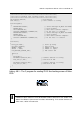
How to find the reference value ?
If the sensor reading value less than the reference value, can interpret the deteced
surface as “Black”
If the sensor reading value more than the reference value, can interpret the
detected surface as “White”
The reference value can calulate from :
(The sensor’s minimum reading value from white surface + The sensor’s maximum
reading value from black surface) / 2
Example
If The sensor’s minimum reading value from white surface is equal 300 andT h e
sensor’s maximum reading value from black surface is equal 100
The reference value will be equal (300+100) / 2 = 200