
User manual


Robotics experiment with PIC microcontroller l 67
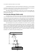
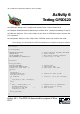
This activity introduces the simple experiment about reading the analog signal.
The simple Variable resistor or Potentiometer is used to analog voltage source and plug
into the analog input port of PIC16F887. You make the simple C code to read the result
from ADC module inside PIC16F887 to display on LCD module.
A5.1 Write the Listing A5-1. Compile and download the code to RBX-877 V2.0 Robot Con-
troller board.
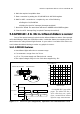
A5.2 Plug the ZX-POTH; potentiometer sensor to RA3 port pin of RBX-877 V2.0 Robot Con-
troller board.
A5.3 Run the program. Adjust the potentiometer and see the result at LCD screen on the
RBX-877 V2.0 Robot Controller board.
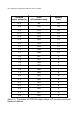
LCD module shows message SENSOR1 = xxx (xxx as 0 to 1023).
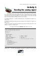
Activity 5
Reading the analog signal
/***********************************/
/***** Show ADC from RA1 to LCD ***/
/***********************************/
char data_[6];
int x;
void main()
{
Delay_ms(1000);
Lcd_Init(&PORTD);
ANSEL = 0xFF; // PORTA ==> Analog
TRISA = 0xFF; // PORTA ==> input
Lcd_Cmd(LCD_CURSOR_OFF); // LCD cursor off
Lcd_Out(1,1,"SENSOR1 = "); // Show Text
ADCON0=0b11001101; // Select Analog1 RC_Mode and ADON
while(1)
{
ADCON0.GO=1;
while(ADCON0.GO);
x= (ADRESH*4)+(ADRESL/64);
WordToStr(x,data_);
Lcd_Out(1,10,data_);
Delay_ms(100);
}
}
Listing A5-1 : The ADC demonstration program for reading the sensor value