
User manual

62l Robotics experiment with PIC microcontroller
5.4.5 Result formatting
The A/D converter result will store in a pair of regeter; ADRESH:ADRESL. They will
keep the data format following the selection of ADFM bit.
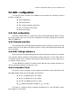
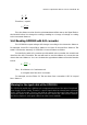
If Left justified is selected (ADFM = ‘0’), ADRESH register keeps 8 upper bits
and ADRESL register keeps 2 lower bits.
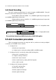
If Right justified is selected (ADFM = ‘1’), ADRESH register keeps 2 upper bits
and ADRESL register keeps 8 lower bits.
b b b b b b b b b b 0 0 0 0 0 0
10-bit Result
# " ! ' & % $ # " !
ADFM = “0” Left justified result
b b b b b b b b b b0 0 0 0 0 0
10-bit Result
# " ! ' & % $ # " !
ADFM = “1” Right justified result
The result data format from ADFM bit selection of ADCON1 register
5.5 A/D Conversion procedure
This is an example procedure for using the ADC to perform an Analog-to-Digital
conversion pf PIC16F887 microcontroller:
1. Configure Port:
l Disable pin output driver
l Configure pin as analog by setting ANSEL or ANSELH register
2. Configure the ADC module (by setting ADCON0 register) :
l Select ADC conversion clock
l Configure voltage reference
l Select ADC input channel
l Select result format by setting ADCON1 register
l Turn on ADC module
3. Configure ADC interrupt (optional):
l Clear ADC interrupt flag
l Enable ADC interrupt
l Enable peripheral interrupt
l Enable global interrupt.