
User manual


60l Robotics experiment with PIC microcontroller
5.2.3 ANSEL : Analog Select register
The ANSEL register is used to configure the Input mode of an I/O pin to analog.
Setting the appropriate ANSEL bit high will cause all digital reads on the pin to be read as
‘0’ and allow analog functions on the pin to operate correctly.
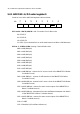
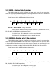
Detail of each bit in ANSEL register is shown below.
ANS7 ANS3
%$#"!
bit
R/W-1
ANS6 ANS5 ANS4 ANS2 ANS1 ANS0
R/W-1 R/W-1 R/W-1R/W-1 R/W-1R/W-1R/W-1
bit 7 to 0 - ANS7 to ANS0 : Analog Select bits
Analog select between analog or digital function on pins AN<7:0> or RE2,
RE1, RE0, RA5, RA3, RA2, RA1 and RA0 respectively.
1 = Analog input. Pin is assigned as analog input (default).
0 = Digital I/O. Pin is assigned to port or special function.
5.2.4 ANSELH : Analog Select High register
The ANSELH register is used to configure the Input mode of an I/O pin to analog.
Setting the appropriate ANSELH bit high will cause all digital reads on the pin to be read
as ‘0’ and allow analog functions on the pin to operate correctly. The port pins which are
controlled by this register consists of AN8 to AN13 (RB2, RB3, RB1, RB4, RB0 and RB5).
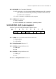
Detail of each bit in ANSELH register is shown below.
- ANS11
%$#"!
bit
R/W-1
- ANS13 ANS12 ANS10 ANS9 ANS8
R/W-1 R/W-1 R/W-1U-0 R/W-1R/W-1U-0
bit 7 and 6 - Unimplemented: Read as ‘0’
bit 5 to 0 - ANS13 to ANS8 : Analog Select bits
Analog select between analog or digital function on pins AN<13:8> or RB5,
RB0, RB4, RB1, RB3 and RB2 respectively.
1 = Analog input. Pin is assigned as analog input.
0 = Digital I/O. Pin is assigned to port or special function.