
User manual


58l Robotics experiment with PIC microcontroller
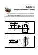
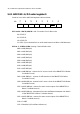
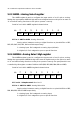
5.2.1 ADCON0 : A/D Control register 0
Detail of each bit in ADCON0 register is shown below.
ADCS1 CHS1
%$#"!
>EJ
R/W-0
ADCS0 CHS3 CHS2 CHS0
GO/
DONE
ADON
R/W-0 R/W-0 R/W-0R/W-0 R/W-0R/W-0R/W-0
bit 7 and 6 - ADCS1, ADCS0 : A/D Conversion Clock Select bits
00 = FOSC/2
01 = FOSC/8
10 = FOSC/32
11 = FRC (clock derived from a dedicated internal oscillator = 500 kHz max)
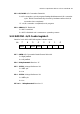
bit 5 to 2 - CHS3 to CHS0 : Analog Channel Select bits
0000 = AN0 (RA0 pin)
0001 = AN1 (RA1 pin)
0010 = AN2 (RA2 pin)
0011 = AN3 (RA3 pin)
0100 = AN4 (RA5 pin)
0101 = AN5 (RE0 pin)
0110 = AN6 (RE1 pin)
0111 = AN7 (RE2 pin)
1000 = AN8 (RB2 pin - reserve for DC motor circuit of the RBX-877V2.0 Robot
Controller board)
1001 = AN9 (RB3 pin - reserve for LED monitor of the RBX-877V2.0 Robot
Controller board)
1010 = AN10 (RB1 pin - reserve for DC motor circuit of the RBX-877V2.0 Robot
Controller board)
1011 = AN11 (RB4 pin - reserve for servo motor output of the RBX-877V2.0
Robot Controller board)
1100 = AN12 (RB0 pin - alternative function wih External Interrput and Swtich
of the RBX-877V2.0 Robot Controller board)
1101 = AN13 (RB5 pin - reserve for servo motor output of the RBX-877V2.0
Robot Controller board)
1110 = CVREF
1111 = Fixed Ref (0.6 volt fixed reference)