
User manual


54 l Robotics experiment with PIC microcontroller
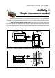
Robo-PICA can control the speed movement by send the signal to the enable
pin (EN) of motor driver IC, L293D. Refer the figure 4-1 (in this chapter), EN pin of L293D is
connected to RC2/CCP1 and RC1/CCP2 port pins of PIC16F887. Both port pins are PWM
output port. Builders can write the program to control the PWM output signal for adjust-
ment motor speed.
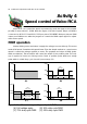
PWM operation
Normal driving motor technique is apply the voltage to motor directly. The motor
works in full speed. Sometime this speed faster. Then the simple method to control motor
speed is control the voltage applied to motor. The populate technique is PWM (pulse-
width modulation). This technique will control the width of the positive pulse. The volt-
age is applied to motor as average value. Ratio of positive pulse width and totally
pulse width is called Duty cycle. Its unit is percentage (%)
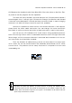
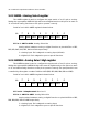
4.8V 4.8V
2.4V
Volt
Time
Volt
Time
50%
duty cycle
Average voltage = 2.4V
Figure A4-1 : Shows average voltage output of PWM
(A) Full volatge apply. (B) 50% duty cycle PWM
(C) 75% duty cycle PWM (D) 25% duty cycle PWM
Activity 4
Speed control of Robo-PICA
(A) (B)
(C) (D)
4.8V
3.6V
Volt
Time
4.8V
1.2V
Volt
Time
75%
duty cycle
Avera
g
e volta
g
e = 3.6V
25%
duty cycle
Avera
g
e volta
g
e = 1.2V