
User manual

46 l Robotics experiment with PIC microcontroller
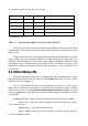
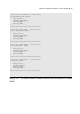
Table 4-1 : Shows logic signal to control motor direction
Motor operation
Shaft free
Shaft locked or Brake
Clockwise turning
anti-clockwise turning
Shaft locked or Brake
12EN/34EN pin
1A/3A pin 2A/4A pin
0 X X
1 0 0
1 0 1
1 1 0
1 1 1
X means logic "0" or "1"
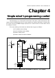
The heart of DC motor driver circuit is the L293D H-Bridge driver (may be replaced
by SN754410). In the Table 4-1 shows all the required signals to control the DC motor
driver circuit.
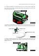
L293D outputs connects to DC motor gearbox and provides LED status for motor
supply voltage. If power is supplied DIRECTLY, the LED will light up in Green. When it is
opposite, if red LED lights up, it means the supply voltage is INVERTED. Builders can use
the different color for defining direction. In other words, if red LED are turned on, the
robot will be moving backwards. If the green LED are turned on, the robot will be mov-
ing forwards.
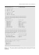
4.1 Motor library file
For better performance and ease of programming, we make the library for driving
and movement controls for the DC motors. It is the motor.h library file. The souce code of
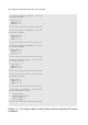
this library is shown in Listing 4-1.
You can use simple text editor t ocreate this library and save as .h file or open
mikroC IDE to create this file. After that copy this library file to the library folder of mikroC
software. The location is C:\Program Files\Mikroelektronika\mikroC\include. You must
copy the motor.h file to this folder. Because the complier will link to this folder for includ-
ing any library.
motor.h library file consists of many functions of movement control. Include :
Motor_Init : Initial the micrococontroller port pin for interfacing the DC
motor driver circuit.
Change_Duty : Control the motor’s speed.
Motor_A_FWD : Drive motor A (M-1 output) to forward direction (LED indi-
cates of M-1 lights in green).