
User manual

Robotics experiment with PIC microcontroller l 45
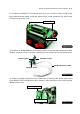
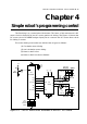
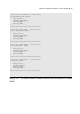
The first thing is to control robot Movement. The heart of this movement is DC
motor circuit. In Robo-PICA has DC motor gearbox in driving. The Figure 4-1 shows the
DC motor circuit. PIC16F887 assigns 6 port pins to connect the DC motor driver circuit
for driving 2 motors.
The motor driving mechanism are divided into 4 types as follows :
(1) Clockwise motor driving
(2) Anti-clockwies motor driving
(3) Motor’s shaft is free
(4) Motor’s shaft is locked or Braked
Chapter 4
Simple robot ’s programming control
Figure 4-1 : The DC motor driver schematic of RBX-877 V2.0 board
RD0
RD1
RB1
RB2
CR1
Ceramic
Resonator
20MHz
13 14
9
2
7
1
15
10
16
13 12 5 4
IC4
L293D
1A
2A
12EN
4A
3A
Vcc1
34EN
1Y
2Y
4Y
3Y
3
6
14
11
R11
2k2
LED4
DIR. #A
LED5
DIR. #B
K18A-K18B
MOTOR-A
K19A-K19B
MOTOR-B
R12
2k2
DIRECT
INVERT
DIRECT
INVERT
+
+
+
+
8
+Vm
35
34
20
19
+5V
R5
4k7
SW2
RESET
R6
1k
+5V
11 32
1
MCLR
+5V
RC2/CCP1
17
RC1/CCP2
16
12
31
IC3
PIC16F887
C6
0.1
µ
F
50V
C9
0.1
µ
F 50V
C8
0.1
µ
F 50V