
User manual

42 l Robotics experiment with PIC microcontroller
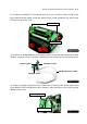
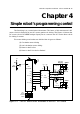
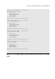
A2.14 Connect the ZX-IRM structure from step A2.12 to the Right angle joiner on the RBX-877
V2.0 controller board from step A2.13. Plug in the Zx-IRM sensor cable to RB0/INT connector.
ZX-IRM
RB0
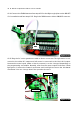
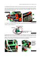
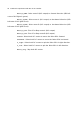
A2.15 Plug the DC motor gearboxes cable to Motor connectors. The right motor is con-
nected to the white M-2 output and left motor is connected to the black M-1 output.
However the motor’s pole (white or black connector) can be changed depending on
the programming and mission. Normally, refer from the motor output’s indicator, if both
light green, it means the forward movement and both light red mean the backward
movement. You can change later if the operation incorrect.
M-1 motor
M-2 motor
Figure A2-17
Figure A2-18