
User manual

Robotics experiment with PIC microcontroller l 41
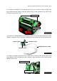
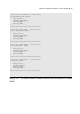
A2.11 Attach the RBX-877 V2.0 controller board on top of robot’s chasis. Please fix the
board with the Power swtch at the side where the DC motor gearboxes are. Secure with
3 Thumb screws at the ends.
Thumbscrew
Thumbscrews
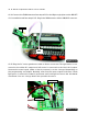
Straight joiner
Obtuse joiner
3x15mm. screw
A2.12 Attach a ZX-IRM 38kHz Receiver module sensor board with the Obtuse joiner using
3x15mm. screw and 3mm. nut. Insert a Straight joiner at another end of the Obtuse joiner.
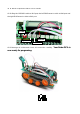
JST3AA-8 sensor cable
Figure A2-14
Figure A2-15
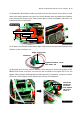
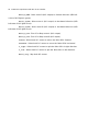
A2.13 Attach a Right angle joiner at the center hole of the back side (Power switch side)
of the RBX-877 V2.0 controller board by a 3x10mm. screw and 3mm. nut for attaching the
ZX-IRM sensor board.
Right angle joiner
3x10mm. screw
Figure A2-16