
User manual

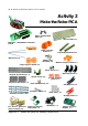

Robotics experiment with PIC microcontroller l 37
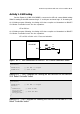
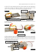
A2.1 Fix 2 of DC motor gearboxes at the base. Turn the extrude side of the right gearbox
out side shown in Figure A2-2. Tighten the 3x10mm. screws from bottom side to fix this
gearbox. Leave the inside hole of the left gearbox. Do not tighten the screw.
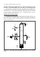
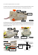
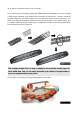
A2.2 Insert the main sprocket to the gearbox’s shaft and fix with 2mm. Wood screw. Do
both DC gearboxes.
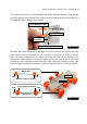
A2.3 Put up side down. Attach the Long angled shaft base with the base at the specific
position as shown in the figure A2-6. Tighten the 3x10mm. screw to a leave hole from step
A2.1.Next, tight a 3x10mm. screw and 3mm. nut to fix the second hole of the Long angled
shaft base as shown in the figure A2-6.
Turn the extrude side to outside
and tight a screw from bottom side
Top side
3x10mm. screw
3x10mm. screw
Bottom side
Leave the
gearboxs hole
Figure A2-2
Figure A2-3
Top side
Main sprocket
2mm. Wood screw
Figure A2-4
Figure A2-5
Hole for tightening a 3x10mm.
screw and 3 mm. nut
Bottom side
3x10mm. screw
Figure A2-6
Long angled
shaft base