
User manual


34l
Robotics experiment with PIC microcontroller
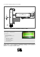
Listing A1-4 : The C program for displaying message on LCD module of
RBX-877 V2.0 Robot Controller board
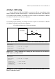
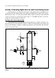
Figure A1-3 : LCD interface schematic of RBX-877 board
+5V
R5
4k7
SW2
4-5-6
R6
1k
+5V
11 32
1
MCLR
DSP1
LCD 16x2 (back light option)
4
6
RS
E
D7 D6 D5 D4 D3 D2 D1 D0 R/W
+5V
BLA
+V
Vo
GNDBLK
JP1
BACK LIGHT
ON
14131211109875 152
3
1
16
R13
47
VR1
10k
BRIGHTNESS
RD2
RD3
21
22
RD7
RD6
RD5
RD4
27
28
29
30
1+!
21+$.&&%
C6
0.1
µ
F
50V
CR1
Ceramic
Resonator
20MHz
13 14
12
31
char *text1 = "Innovative";
char *text2 = "Experiment";
void main()
{
Lcd_Init(&PORTD);
Lcd_Cmd(LCD_CURSOR_OFF);
while(1)
{
Lcd_Out(1,1,text1);
Lcd_Out(2,1,text2);
Delay_ms(5000);
Lcd_Cmd(LCD_CLEAR);
Delay_ms(500);
}
}
INNOVATIVE EXPERIMENT