
User manual


Robotics experiment with PIC microcontroller l 33
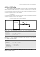
Listing A1-3 : The C program of reading digital value from the Switch input
at RA4 pin to control the sound generation of Piezo speaker at RC0 pin. The
operation is similar the door chime.
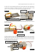
Testing
A1.2.1 Write the Listing A1-3. Compile and download the code to RBX-877 board.
A1.2.2 Press the switch at RA4 and observe the operation of the Piezo speaker on the
RBX-877 V2.0 Robot Controller board.
Listen sound from the piezo speaker following the switch pressing.
void main()
{
Sound_Init(&PORTC, 0); // Init Sound
while(1)
{
if (!PORTA.F4) // Test RA4 keypress
sound_play(250,50); // 2kHz sound ON RC0
}
}
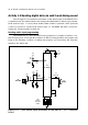
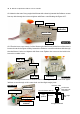
Activity 1-3 Show message on LCD module
The RBX-877 V2.0 Robot Controller board provides the connector to interface
LCD moudule. The schematic diagram is shown in the Figure A1-3. User must use this
information to define in the C program for mikroC compiler knows the port pin that use
in this interface.
When interfacing, you wil require 6 port pins which includes the RD2 for RS pin of
LCD module, RD3 for E pin and RD4 to RD7 for data pin D4 to D7 in 4-bit interface mode.
The R/W pin of LCD is connected to ground for only writing all data to LCD. With this
connection, help developers to make the C code for interfacing the LCD module easier.
Because you can use the LCD built-in function of mikroC compiler; Lcd_Init(&PORTD).
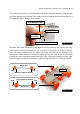
Testing
A1.3.1 Write the Listing A1-4. Compile and download the code to RBX-877 V2.0 Robot
Controller board.
A1.3.2 Observe the operation.
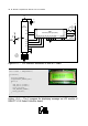
At LCD module show message Innovative on the upper line and Experiment on
the lower line. If need to use the back-light LED, put jumper at LCD backlight position.