
User manual


32l
Robotics experiment with PIC microcontroller
Activity 1-2 Reading digital data via switch and driving sound
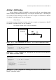
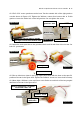
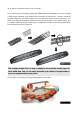
See the figue A1-2, it shows the schematic of the switch input of the RBX-877 V2.0
Controller board. The switch tested in this activity is the RA4-switch. If switch is not pressed,
DATA point as logic “1” from pull-up resistor 10kΩ. If switch is pressed, DATA point will
connect to ground. It causes DATA point is logic “0”. PIC16F887 will drive a sound fol-
lowing the activated swtich at RA4 pin.
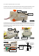
Reading switch input programming
The easiest way to check this switch being pressed in C program of mikroC com-
piler is looping and check with IF command. If switch is being pressed, the program will
jump to the following condition. In writing the program, you must select the port that
interface the switch first.
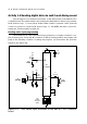
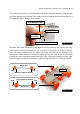
Figure A1-2 : RA4 Switch input schematic of the RBX-877 V2.0 Controller
board
6
+5V
R5
4k7
SW2
RESET
R6
1k
+5V
11 32
1
MCLR
+5V
R8
4k7
R7
4k7
RA4
RB0/INT
K7
INT/RB0
+5V
R9
150
33
RC0
SP1
PIEZO
15
12
31
1+!
21+$.&&%
C6
0.1
µ
F
50V
C7
10
µ
F 50V
CR1
Ceramic
Resonator
20MHz
13 14