
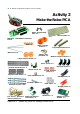
User manual


Robotics experiment with PIC microcontroller l 31
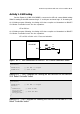
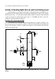
Activity 1-1 LED testing
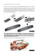
See the Figure A1-1, RB3 of PIC16F887 is connected to LED via current limited resistor
510Ω. For turning-on this LED must send logic “1” to this port. and send logic “0” for turning-off.
A1.1.1 Write program following the Listing A1-1 then compile and download to RBX-877
V2.0 Robot Controller board. See the operation.
LED at RB3 on.
A1.1.2 Write program following the Listing A1-2 then compile and download to RBX-877
V2.0 Robot Controller board. See the operation.
LED at RB3 will blink with 0.5 second duration.
Figure A1-1 : LED connection on RBX-877 V2.0 Robot Controller board
21+$.&&%
!$
4*!
R9
510
LED3
4*!
void main()
{
TRISB.F3=0; // Set RB3 ==> Output
PORTB.F3=1; // Turn on RB3
}
Listing A1-1 : The C program for Turning on the RB3-LED of the RBX-877
V2.0 Robot Controller board
void main()
{
TRISB.F3=0; // Set RB3 ==> Output
while(1)
{
PORTB.F3=1; // Turn on RB3
Delay_ms(500);
PORTB.F3=0; // Turn off RB3
Delay_ms(500);
}
}
Listing A1-2 : The C program for Blinking the RB3-LED of the RBX-877 V2.0
Robot Controller board