
User manual


Robotics experiment with PIC microcontroller l 29
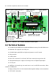
2.2.5 Programmable port
The RBX-877 V2.0 board provides 9-programmable multipurpose ports. It includes
RA0-RA3, RA5, RE0-RE2 and RB0 pin. All port pin can program to 3 functions as
(1) Analog input - to get analog signal to A/D converter circuit inside
microcontroller. Input voltage range is 0 to 5V. Converter resolution is 10-bit.
(2) Digital input - to get digital signal from digital device and switch.
(3) Digital output - to drive digital signal logic “0” and “1” to external device.
In default all port will be set to analog input port.
On RBX-877 V2.0 board provides all ports in 3-pin JST connector. Each connector
includes +5V and GND.
2.2.6 UART port for serial data wired/wireless communication
Builders can make the serial data communication from RBX-877 V2.0 board to
computer’s RS-232 serial port and many wireless serial device such as XBEE module and
Bluetooth. PIC16F887 microcontroller provides RC6 and RC7 pin UART module port pin
for this purpose. Serial signal from PIC16F887’s are connected to 2 free JST connectors
for support all serial device.
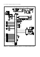
2.2.7 DC motor driver circuit
The RBX-877 V2.0 board use IC4, L293D H-bridge motor driver IC are used for
driving 2 channel DC motors. The suitable motor is 4.5-6V 100 to 200mA or up to 400mA.
Motor A speed is controlled by RD0 with RD1 pin and enable by RC2 port. Motor
B speed is controlled by RB1 with RB2 pin and enable by RC1. LED4 and LED5 are bi-color
LED. They are used for showing the motor output status.
Voltage is supplied to L293D includes +5V supply voltage and Motor supply volt-
age (+Vm). The +Vm is concentrated direct from batteries for powerful driving.
2.2.8 RC servo motor driver circuit
The RBX-877 V2.0 Controller board provides 3 port pins for RC servo motors. It
includes RB4, RB5 and RC5 . RC servo motor supply comes from system battery. This driver
cannot support high-current and high power RC servo motor. The suitable RC servo
motor is 4.8 to 6V motor and need current consumption about 100-200mA.
2.2.9 I
2
C connector
A way to expansion of RBX-877 V2.0 board is using a I
2
C bus connector. Many
external device need I
2
C bus protocol such as Real-time clock, memory, A/D and D/A
converter, Port expansion device and etc. RC3/SCL and RC4/SDA of PIC16F887 are
connected to I
2
C bus connector includes +5V supply and GND. No any pull-up resistor
are connected to theses port. User must provides them at the external devices.