
User manual


Robotics experiment with PIC microcontroller l 27
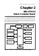
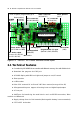
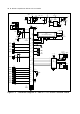
2.2 RBX-877 V2.0 board circuit description
2.2.1 Microcontroller circuit
The heart of this board is the PIC16F887 microcontroller. The 20MHz ceramic reso-
nator, CR1 is used to make the 20MHz clock for PIC16F887.
2.2.2 Power supply
The RBX-877 V2.0 board contains a step-up switching power supply to supply +5V
regulated for PIC16F887. Although the level of battery will decrease when driving the
motor. This switching power supply circuit will maintain the +5V for microcontroller until
battery voltage level down to 1.5V
S1 is on-off switch to supply the voltage from batteries to RBX-877 V2.0 board. R3,
D1 and ZD1 ard used to limit the input voltage to IC2 not over 5.1V
IC1 is a switching power supply IC, NCP1450-5.0. It can support input voltage 1.5
to 4.2V range for regulating +5V supply voltage. ZD2 is used to limit output voltage of
NCP1450-5.0 not over +5V.
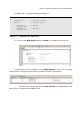
2.2.3 In-System Programming circuit
The RBx-877 V2.0 board require In-system programming via ICD2 or ISP connec-
tor. The USB programmer which is bundled in the Robo-PICA kit will connect to ICD2
jack of the RBX-877 V2.0 controller board. It use the supply voltage from USB port of
computer.
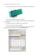
The programming signal will send to RB6 and RB7 pin of PIC16F887. The high volt-
age programming is sent to MCLR pin. All programming status would be show on the
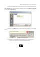
PICkit2 Programming software on computer’s monitor. After programming complete,
this controller can work suddenly.
2.2.4 Display circuit
Character display : The RBX-877 V2.0 board provides LCD module connector. It
supports 16 characters 2 lines LCD. PIC16F877’s RD4 to RD7 pin are assigned to D4 to D7
data pins, RD3 to E pin and RD2 to RS pin for selection data mode. VR1 is used to contrast
adjustment of LCD screen. In case using Back-light LCD, it provides a jumper to control
the LED back-light of LCD.
LED monitor : RBX-877 V2.0 board has a general purpose LED. They are con-
nected to RB3 of PIC16F887 microcontroller via a current limited resistor.
Sound output : RBX-877 V2.0 board has a sound driver circuit. Connect RC0 pin to
a piezo speaker via a capacitor 10µF. This circuit can drive audio frequency signal.
However the piezo speaker has the resonance frequency of range 1kHz to 3kHz.