
User manual


26l
Robotics experiment with PIC microcontroller
2.1 Technical features
l Controlled by PIC16F887 Microcontroller with 8Kword memory. Run with 20MHz clock
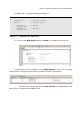
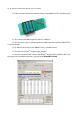
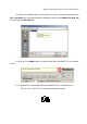
l Download the program via ICD2 jack.
l LCD16x2 display with LED back light and jumper to on/off control
l Piezo speaker
l a LED monitor
l Drive 2-DC motors 4.5V to 6V and 3-RC Servo motors (in range 4.8 to 6V)
l 9-Programmable ports support all analog inout and digtial input/output
l I
2
C bus port
l UART port for interfacing the serial device such as RS-232 transceiver, XBee
module and Bluetooth.
l Supply voltage from 4 of AA batteries (Rechargable battery is recommended)
l 2.375 x 6.25 Inches size
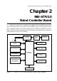
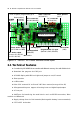
Figure 2-2 : RBX-877 V2.0 Robot controller board layout
ICD2 in-system programming jack
Battery terminal
POWER
switch
DC motor output
(connect RC2, RD0, RD1
and RC1, RD2, RD3)
Servo motor output
(RC5, RB4 and RB5)
Interrupt switch
(RB0/INT)
Programmable I/O port
(RA0-RA3, RA5, RE0-RE2)
LCD connector
(RD2, RD3, RD4-RD7)
Piezo speaker
(RC0 )
LED monitor
(RB3)
I
2
C connector
(RC3 and RC4)
PIC16F887 microcontroller
UART connector
(RC6 and RC7)
Interrupt port
RA4 switch
LOW BAT.
indicator