
User manual


Robotics experiment with PIC microcontroller l 25
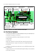
Robo-PICA robotic kit is controlled by the RBX-877 V2.0 (PIC16F887 Robot Experi-
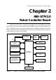
ment board). The main microcontroller is the PIC16F887. Figure 2-1 shows operating dia-
gram of RBX-877 board. In this chapter will present the operation of RBX-877 board and
some example experiment. Builders must read and test all experiments for building and
programming the robot in next chapter.
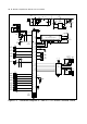
ICD2 Programming
interface
UART Serial interface
Programmable Analog
input and Digital
Input/Output port
I
C bus interface
Driving RC servo
motor circuit
Driving DC motor
circuit
Driving
Piezo speaker
LCD module
interface
+5V Switching
power supply
Battery
supply
(AA x4)
Low Battery
status circuit
PIC16F887
microcontroller
+5V
20MHz clock circuit
+5V
Figure 2-1 : RBX-877 V2.0 Robot controller boards block diagram
Chapter 2
RBX-877V2.0
Robot Controller Board