Robotics experiment with PIC microcontroller l 1 Robotics experiment with PIC microcontroller based-on Robo-PICA robot kit 3rd Edition (C) Innovative Experiment Co.,Ltd.
l Robotics experiment with PIC microcontroller Contents Chapter 1 Part list of Robo-PICA and Introduce software tools...............5 1.1 Robo-PICA part list 1.2 Hand tools for making robot kit 1.3 Software development tools for Robot programming Chapter 2 RBX-877V2.0 Robot Controller board...................................25 2.1 Technical features 2.2 Circuit description Activity 1 : Write programs for testing RBX-877 V2.0 Controller board Chapter 3 Building Robo-PICA kit...........................
Robotics experiment with PIC microcontroller l 3 Chapter 6 Line following mission..............................................................71 6.1 Infrared reflector sensor Activity 8 : Reading the Line tracking sensor Activity 9 : Moves follow the black line Chapter 7 Remote control experiment...................................................79 7.1 38kHz Infrared receiver module 7.
l Robotics experiment with PIC microcontroller
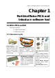
Robotics experiment with PIC microcontroller l 5 Chapter 1 Part list of Robo-PICA and Introduce software tool 1.1 Robo-PICA part list There are 2 groups : 1.1.1 Mechanical parts 1.1.2 Electronic parts 1.1.1 Mechanical parts Motor Gearbox – Uses a 4.5V (9V max.) and 180 mA DC motor with a ratio of 48:1; torque 4kg/cm; comes with the mounting.
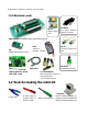
l Robotics experiment with PIC microcontroller 1.1.2 Electronic parts ZX-01 Switch input (x2) GP2D120 4 to 30cm. Infrared Distance sensor RBX-877V2.0 PIC16F887 Robot Experiment Board ZX-IRM 38kHz Infrared Receiver ER-4 Infrared Remote Control ZX-03 Infrared Reflector (x2) ZX-POTH Potentiometer (x1) USB cable USB Programmer board with ICD2 cable 4 of AA batteries (Rechargable battery is recommended - not include this kit) 1.
Robotics experiment with PIC microcontroller l 7 1.3 Software development tools for Robot programming The RoboPICA kit uses the PIC Micrcontroller PIC16F887. Builders can write the controlled program in assembly, BASIC and C language. Only BASIC and C program language requires the use of a compiler software. However in this kit all examples are in C language with mikroC compiler from mikroElektronika (mikroE : www.mikroe.com). The Robo-PICA robot kit can use this compiler as well.
l Robotics experiment with PIC microcontroller l Monitor your program structure, variables, and functions in the Code Explorer. Generate commented, human-readable assembly, and standard HEX compatible with all programmers. l Inspect program flow and debug executable logic with the integrated Debugger. Get detailed reports and graphs on code statistics, assembly listing, calling tree… l mikroE have provided plenty of examples for you to expand, develop, and use as building bricks in your projects.
Robotics experiment with PIC microcontroller l 9 (A) Install of the Microsoft .NET Framework First thing to do is to install the Microsoft.NET Framework. Select from the folder PICkit 2 Setup v2.01 dotNET à dotnetfx in the bundled CD-ROM. Double-click at dotnetfx.exe file. After complete, install the PICkit2TM Programming Software by doubleclick at PICkit2Setup.msi file. The software installation will start. (B) Microsoft .
l Robotics experiment with PIC microcontroller 1.3.2.2 Using PICkit2TM Programming Software 1.3.2.2.1 Testing hardware connection (1) Connect the USB cable between the programmer and Computer’s USB port. Open the software Pickit2TM Programming Software by entering the Start à All programs à Microchip à Pickit 2 V201. The main window will appear as shown in figure 1-1. (2) On successful connnection, the message PICkit 2 found and connected will appear in the Status box.
Robotics experiment with PIC microcontroller l 11 (3) If the connection is incompleted. The message PICkit 2 not found. Check USB connections and use Tools à Check Communication to retry will appear in the Status box. Check the cables and connections. (4) Go to Tools menu and select Check Communication command. If all’s correct, the message PICkit 2 found and connected will be show in the Status box.
l Robotics experiment with PIC microcontroller 1.3.2.2.2 Command menu description FILE • Import File – Import a hex file for programming • Export File – Export a hex file read from a device • Exit – Exit the program (duplicated with the Quit button) DEVICE FAMILY • Baseline (12-bit Core) – Configures the programming software for baseline Flash devices • Mid-range - Configures the programming software for 14-bit core flash devices.
Robotics experiment with PIC microcontroller l 13 PROGRAMMER • Read Device – Reads the program memory, data EEPROM memory, ID locations, and Configuration bits. • Write Device – Writes the program memory, data EEPROM memory, ID locations, and Configuration bits. • Verify – Verifies the program memory, data EEPROM memory, ID locations and Configuration bits read from the target MCU against the code stored in the programming software. • Erase – Performs a bulk erase of the target MCU.
l Robotics experiment with PIC microcontroller • Fast Programming - Select the PX-200 to programs the Flash device with high speed. • Check Communication – Verifies communication with the USB Programmer and reads the device ID of the target MCU. • Download PICkit 2 Firmware – Performs a download of the USB Programmer firmware operating system. (this USB programmer is compatible PICkit2TM Programmer). Sometime call this function to OS update.
Robotics experiment with PIC microcontroller l 15 (b) Access only Flash program memory Click at Enabled box in EEPROM data border to remove the mark. At EEPROM data border will show Preserve device EEPROM data on write in red message. It means the EEPROM data memory will be protected. User can access only Flash program memory. See the illlustration below. 1.3.2.3 Updating the USB Programmer Firmware To update the programmer firmware Operating System, complete the following steps.
l Robotics experiment with PIC microcontroller (3) Browse to the directory where the latest Operating System code was saved, Select the PK2*.hex file and click on the Open button as shown in figure below. (4) The progress of the OS update will be displayed in the status bar of the programming software and the Busy LED on the USB Microcontroller Programmer will flash. When the update completes successfully, the status bar will display “Operating System Verified” and the Busy LED will go out.
Robotics experiment with PIC microcontroller l 17 1.4 Programming devleopment for Robo-PICA The summary of steps of program the Robo-PICA robot kit are as follows : 1. Create the C project file with mikroC IDE software. 2. Compile the project file. 3. If any error occurs, edit the C program to fix the error and compile the project file until all are correct. 4. The HEX file would be created after the compilation is completed. 5. Open the PICkit2TM Programming software.
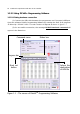
l Robotics experiment with PIC microcontroller Complie button Program editor area Target microcontroller device Clock frequency of microcontroller Output window Figure 1-1 : The main window of mikroC IDE and the important components need to know.
Robotics experiment with PIC microcontroller l 19 1.5.4 Create the new project file by entering to menu Project and select New Project... 1.5.5 The New Project window will appear.
l Robotics experiment with PIC microcontroller (a) Project Name : Put the project name. mikroC IDE will create the folder to support your project file which includes the C sourcecode. For example is Blink_LED project file. (b) Project Path : Select the location of your project file. Click the Browse button to select the location. For example is D:\ROBO-PICA (c) Description : Put the information of your porject file.
Robotics experiment with PIC microcontroller l 21 1.5.6 Type the C program following the Listing 1-1. void main() { TRISB.F3=0; while(1) { PORTB.F3=0; Delay_ms(500); PORTB.F3=1; Delay_ms(500); } } // Set RB3 as Output // Infinite Loop // LED_ON // LED_OFF Listing 1-1 : Blinking LED test code 1.5.7 Click on the Build Project button or Ctrl+F9 for compiling the project file. 1.5.8 Observe the error message at the Output window.
l Robotics experiment with PIC microcontroller 1.5.9 Put 4 of AA batteries into battery holder of the RBX-877V2.0 Controller board. 1.5.10 Connect the USB programer with PC’s USB port 1.5.11 Connect the ICD2 cable between the USB programmer and the RBX-877V2.0 Controller board. 1.5.12 Turn-on the power to the RBX-877 V2.0 Controlller board. 1.5.13 Open the PICkit2TM Programming software. 1.5.
Robotics experiment with PIC microcontroller l 23 1.5.15 Select the HEX fle which require program to microcontroller by entering menu File à Import Hex. The open HEX file window will appear. Select to D:\ROBO-PICA\Blink_LED for selecting the Blink_LED.hex 1.5.16 Click on the Write button to download HEX file to the RBX-877 V2.0 Controlller board. 1.5.17 Observe the result at RB3 LED on the RBX-877 V2.0 Controlller board. RB3 LED of the RBX-877V2.0 Controller board blinks always.
l Robotics experiment with PIC microcontroller
Robotics experiment with PIC microcontroller l 25 Chapter 2 RBX-877V2.0 Robot Controller Board Robo-PICA robotic kit is controlled by the RBX-877 V2.0 (PIC16F887 Robot Experiment board). The main microcontroller is the PIC16F887. Figure 2-1 shows operating diagram of RBX-877 board. In this chapter will present the operation of RBX-877 board and some example experiment. Builders must read and test all experiments for building and programming the robot in next chapter.
l Robotics experiment with PIC microcontroller Piezo speaker UART connector (RC6 and RC7) (RC0 ) LCD connector I2C connector (RD2, RD3, RD4-RD7) (RC3 and RC4) ICD2 in-system programming jack Battery terminal POWER LOW BAT.
Robotics experiment with PIC microcontroller l 27 2.2 RBX-877 V2.0 board circuit description 2.2.1 Microcontroller circuit The heart of this board is the PIC16F887 microcontroller. The 20MHz ceramic resonator, CR1 is used to make the 20MHz clock for PIC16F887. 2.2.2 Power supply The RBX-877 V2.0 board contains a step-up switching power supply to supply +5V regulated for PIC16F887. Although the level of battery will decrease when driving the motor.
l Robotics experiment with PIC microcontroller S1 POWER +Vm - 1 +V C2 0.1/50V K1 DC input GND 2 L1 10µH D2 MBRA340T3 +5V C3 100µF 10V IC1 KIA7042 ZD1 5.
Robotics experiment with PIC microcontroller l 29 2.2.5 Programmable port The RBX-877 V2.0 board provides 9-programmable multipurpose ports. It includes RA0-RA3, RA5, RE0-RE2 and RB0 pin. All port pin can program to 3 functions as (1) Analog input - to get analog signal to A/D converter circuit inside microcontroller. Input voltage range is 0 to 5V. Converter resolution is 10-bit. (2) Digital input - to get digital signal from digital device and switch.
l Robotics experiment with PIC microcontroller Activity 1 Write programs for testing RBX-877 V2.0 Controller board Procedure For all activities of the programming development for Robo-PICA robot kit have the summary of steps are as follows : 1. Create the C project file with mikroC IDE software. 2. Compile the project file. 3. If any error happens, edit the C program to fix the error and compile the project file until all are correct. 4.
Robotics experiment with PIC microcontroller l 31 Activity 1-1 LED testing See the Figure A1-1, RB3 of PIC16F887 is connected to LED via current limited resistor 510Ω. For turning-on this LED must send logic “1” to this port. and send logic “0” for turning-off. A1.1.1 Write program following the Listing A1-1 then compile and download to RBX-877 V2.0 Robot Controller board. See the operation. LED at RB3 on. A1.1.2 Write program following the Listing A1-2 then compile and download to RBX-877 V2.
l Robotics experiment with PIC microcontroller Activity 1-2 Reading digital data via switch and driving sound See the figue A1-2, it shows the schematic of the switch input of the RBX-877 V2.0 Controller board. The switch tested in this activity is the RA4-switch. If switch is not pressed, DATA point as logic “1” from pull-up resistor 10kΩ. If switch is pressed, DATA point will connect to ground. It causes DATA point is logic “0”. PIC16F887 will drive a sound following the activated swtich at RA4 pin.
Robotics experiment with PIC microcontroller l 33 Testing A1.2.1 Write the Listing A1-3. Compile and download the code to RBX-877 board. A1.2.2 Press the switch at RA4 and observe the operation of the Piezo speaker on the RBX-877 V2.0 Robot Controller board. Listen sound from the piezo speaker following the switch pressing. void main() { Sound_Init(&PORTC, 0); while(1) { if (!PORTA.
l Robotics experiment with PIC microcontroller +5V 11 32 C6 0.1µF 50V +5V 1+! 21+ $.
Robotics experiment with PIC microcontroller l 35 Chapter 3 Building Robo-PICA kit This chapter describes about how to building the Robo-PICA robot kit.
l Robotics experiment with PIC microcontroller Activity 2 Make the Robo-PICA Short angled shaft base x 2 Universal Plate x 1 RBX-877 PIC16F887 controller board Hub x 6 Main sprocket wheel x 2 Long angled shaft base x 2 Metal axel x 3 30mm. Hex standoffs x 3 Large support wheel x 2 Medium support wheel x 2 3mm. spacer x 2 Right angle joiners x 3 30-joint track wheel x 2 Thumb screw x 3 10-joint track wheel x 4 3x10mm. Screw x 15 3-hold Straight joiner x 2 2mm. Wood screw x 2 3x15mm.
Robotics experiment with PIC microcontroller l 37 A2.1 Fix 2 of DC motor gearboxes at the base. Turn the extrude side of the right gearbox out side shown in Figure A2-2. Tighten the 3x10mm. screws from bottom side to fix this gearbox. Leave the inside hole of the left gearbox. Do not tighten the screw. Leave the gearboxs hole Figure A2-2 3x10mm. screw Top side Bottom side Turn the extrude side to outside and tight a screw from bottom side Figure A2-3 3x10mm. screw A2.
l Robotics experiment with PIC microcontroller A2.4 Attache the rest of Long angled shaft base with a base by inserted the 3x10mm. screws from top side through the hole and tighten with 3mm. nuts following the Figure A2-7. 3mm. nut 3mm. nut Long angled shaft base Bottom side 3mm. nut Figure A2-7 A2.5 Turn the base over. Attach 2 of the Short angled shaft bases at the front of the robot’s base as shown in the Figure A2-8 by inserted the 3x10mm.
Robotics experiment with PIC microcontroller l 39 A2.7 At front side, attach 2 of the Hexagonal standoffs. Insert the 3x10mm. screw through the 3-hole straight joiner and the leave hole of the short angled shaft base from step A2.5 to fix with the 30mm. Hexagonal standoffs. 3-Hole Straight joiner Bottom side 3x10mm. screw Short angled shaft base 30mm. Hexagonal Standoff Figure A2-10 A2.
l Robotics experiment with PIC microcontroller A2.9 Create two track belts by putting the different size tracks together. One track would consist of the following: One 30-joint track and two 10-joint tracks. Connect all tracks together. Take one end and connect it to the other end of the track to form one complete loop. Repeat the steps to make two track sets.
Robotics experiment with PIC microcontroller l 41 A2.11 Attach the RBX-877 V2.0 controller board on top of robot’s chasis. Please fix the board with the Power swtch at the side where the DC motor gearboxes are. Secure with 3 Thumb screws at the ends. Thumbscrews Thumbscrew Figure A2-14 A2.12 Attach a ZX-IRM 38kHz Receiver module sensor board with the Obtuse joiner using 3x15mm. screw and 3mm. nut. Insert a Straight joiner at another end of the Obtuse joiner. 3x15mm.
l Robotics experiment with PIC microcontroller A2.14 Connect the ZX-IRM structure from step A2.12 to the Right angle joiner on the RBX-877 V2.0 controller board from step A2.13. Plug in the Zx-IRM sensor cable to RB0/INT connector. ZX-IRM RB0 Figure A2-17 A2.15 Plug the DC motor gearboxes cable to Motor connectors. The right motor is connected to the white M-2 output and left motor is connected to the black M-1 output.
Robotics experiment with PIC microcontroller l 43 A2.16 Install the ZX-03 Infrared reflector sensor board at the bottom of the robot’s chasis. Attach the sensor with the end hole of the 3-hole Straight joiner by inserted the 3x10mm. screw through the sensor board, 3mm. plastic spacer, joiner and tighten with 3mm. nut. Install both side; left and right. Figure A2-19 Infrared reflector sensors 3mm. nut 3mm. spacer Figure A2-20 A2.
l Robotics experiment with PIC microcontroller A2.19 Plug the GP2D120 cable to RA2 port, the left ZX-03 sensor’s cable to RA0 port and the right ZX-03 sensor’s cable to RA1 port. ZX-IRM Right ZX-03 GP2D120 Left ZX-03 A2.20 Arrange all cables and check all connection carefully. now ready for programing.
Robotics experiment with PIC microcontroller l 45 Chapter 4 Simple robot ’s programming control The first thing is to control robot Movement. The heart of this movement is DC motor circuit. In Robo-PICA has DC motor gearbox in driving. The Figure 4-1 shows the DC motor circuit. PIC16F887 assigns 6 port pins to connect the DC motor driver circuit for driving 2 motors.
l Robotics experiment with PIC microcontroller 12EN/34EN pin 1A/3A pin 2A/4A pin Motor operation 0 X X Shaft free 1 0 0 Shaft locked or Brake 1 0 1 Clockwise turning 1 1 0 anti-clockwise turning 1 1 1 Shaft locked or Brake X means logic "0" or "1" Table 4-1 : Shows logic signal to control motor direction The heart of DC motor driver circuit is the L293D H-Bridge driver (may be replaced by SN754410).
Robotics experiment with PIC microcontroller l 47 char motor_duty_= 127; char motor_init_=0; // // // // *** Motor A PD0 ====> PD1 ====> PC2 ====> ***** 1A 1B 1E (PWM1) // // // // *** Motor B PB1 ====> PB2 ====> PC1 ====> ***** 2A 2B 2E (PWM2) // Defalt PWM 50% // Status initial //**************************************************** //********** Initial Motor Function ****************** //**************************************************** void Motor_Init() { if (motor_init_==0) // First time ? {
l Robotics experiment with PIC microcontroller /********** Motor B Forward ********/ void Motor_B_FWD() { Pwm2_Start(); PORTB.F1 =0; PORTB.F2 =1; } /************************************/ /********** Motor A Backward *******/ void Motor_A_BWD() { Pwm1_Start(); PORTD.F0 =1; PORTD.F1 =0; } /************************************/ /********** Motor B Backward *******/ void Motor_B_BWD() { Pwm2_Start(); PORTB.F1 =1; PORTB.
Robotics experiment with PIC microcontroller l 49 /********** Go Backward ************/ void Backward(char speed) { Motor_Init(); Change_Duty(speed); Motor_A_BWD(); Motor_B_BWD(); } /************************************/ /********** Spin Left *************/ void S_Right(char speed) { Motor_Init(); Change_Duty(speed); Motor_A_FWD(); Motor_B_BWD(); } /************************************/ /********** Spin Right ************/ void S_Left(char speed) { Motor_Init(); Change_Duty(speed); Motor_A_BWD(); Motor_B_
l Robotics experiment with PIC microcontroller Motor_B_FWD : Drive motor B (M-2 output) to forward direction (LED indicates of M-2 lights in green). Motor_A_BWD : Drive motor A (M-1 output) to backward direction (LED indicates of M-1 lights in red). Motor_B_BWD : Drive motor B (M-2 output) to backward direction (LED indicates of M-2 lights in red). Motor_A_off : Turn off or Stop motor A (M-1 output). Motor_B_off : Turn off or Stop motor B (M-2 output).
Robotics experiment with PIC microcontroller l 51 Activity 3 Simple movement control Robo-PICA moves forward or backward by driving both DC motor gearboxes in same direction and at the same time. If need to turn or rotate, below shows the method : 1. Stop one motor and Drive another one If stop left motor and drive right motor, the robot will turn left. In the opposite direction, stop right motor and drive left motor. The robot will turn right. The speed of movement is similar.
l Robotics experiment with PIC microcontroller 2. Drive both motors in opposite direction If the left motor drives forward and right motor drives backward, the robot will rotate right direction. If its in the opposite direction, the left motor drives backward and right motor drives forward. The robot will rotate left direction instead. In this method the speed of rotation will be increase 2 times and less friction. The turning point is center of robot body. See Figure A3-2. A3.
Robotics experiment with PIC microcontroller l 53 A3.2 Remove the downlaod cable from Robo-PICA. Place the robot on the floor. Turnon power to run the program. See the operation. The robot will move forward 2 seconds and spin left 0.8 second and foward 2 seconds again. Next, it will spin right 0.8 second to change the direction and forward 2 seconds, moves backward 1 second and stop movement finally. In each changing movement, thr robot will beep a sound to report the operation.
l Robotics experiment with PIC microcontroller Activity 4 Speed control of Robo-PICA Robo-PICA can control the speed movement by send the signal to the enable pin (EN) of motor driver IC, L293D. Refer the figure 4-1 (in this chapter), EN pin of L293D is connected to RC2/CCP1 and RC1/CCP2 port pins of PIC16F887. Both port pins are PWM output port. Builders can write the program to control the PWM output signal for adjustment motor speed.
Robotics experiment with PIC microcontroller l 55 #include char i; void main() { Forward(255); while(1) { Delay_ms(2000); Pwm1_Change_Duty(220); Pwm2_Change_Duty(255); Delay_ms(5000); Pwm1_Change_Duty(255); } } // Motor Forward // Motor A // Motor B 85% Duty 100% Duty // Motor A 100% Duty Listing A4-1 : The speed control program for Robo-PICA by using PWM. For Robo-PICA, we prepare the speed control with PWM technique via software by the motor.h library file. You can see detail in motor.
l Robotics experiment with PIC microcontroller
Robotics experiment with PIC microcontroller l 57 Chapter 5 Contactless object detection The one of most important function of mobile robot is interfacing the sensors. RoboPICA can interface with many type of sensors. Because it has both digital and analog inputs. PIC16F887 the main microcontroller of Robo-PICA has many ports. We assign 9 programmable port pins for supporting the analog and digital sensors. In addtion 2 types of serial coomunication ports; UART and I2C bus.
l Robotics experiment with PIC microcontroller 5.2.1 ADCON0 : A/D Control register 0 Detail of each bit in ADCON0 register is shown below.
Robotics experiment with PIC microcontroller l 59 bit 1- GO/DONE: A/D Conversion Status bit 1 = A/D conversion cycle in progress. Setting this bit starts an A/D conversion cycle. This bit is automatically cleared by hardware when the A/D conversion has completed. “0” = A/D conversion completed/not in progress bit 0 - ADON: ADC Enable bit 1 = ADC is enabled 0 = ADC is disabled and consumes no operating current 5.2.2 ADCON1 : A/D Control register 1 Detail of each bit in ADCON1 register is shown below.
l Robotics experiment with PIC microcontroller 5.2.3 ANSEL : Analog Select register The ANSEL register is used to configure the Input mode of an I/O pin to analog. Setting the appropriate ANSEL bit high will cause all digital reads on the pin to be read as ‘0’ and allow analog functions on the pin to operate correctly. Detail of each bit in ANSEL register is shown below.
Robotics experiment with PIC microcontroller l 61 5.3 ADC configuration For using the ADC module of PIC16F887 microcontroller the following functions must be considered: l Port configuration l Channel selection l ADC voltage reference selection l ADC conversion clock source l Results formatting 5.4.1 Port configuration The ADC can be used to convert both analog and digital signals. When converting analog signals, the I/O pin should be configured for analog by setting the associated TRIS and ANSEL bits.
l Robotics experiment with PIC microcontroller 5.4.5 Result formatting The A/D converter result will store in a pair of regeter; ADRESH:ADRESL. They will keep the data format following the selection of ADFM bit. If Left justified is selected (ADFM = ‘0’), ADRESH register keeps 8 upper bits and ADRESL register keeps 2 lower bits. If Right justified is selected (ADFM = ‘1’), ADRESH register keeps 2 upper bits and ADRESL register keeps 8 lower bits.
Robotics experiment with PIC microcontroller l 63 4. Wait the required acquisition time. 5. Start conversion by setting the GO/DONE bit in ADCON0 register. 6. Wait for ADC conversion to complete by one of the following: l Polling the GO/DONE bit l Waiting for the ADC interrupt (interrupts enabled) 7. Read ADC Result. The result data will store in ADRESH and ADRESL register. 8. Clear the ADC interrupt flag (required if interrupt is enabled). 5.6 GP2D120 : 4 to 30cm.
l Robotics experiment with PIC microcontroller GP2D120 Infrared Ranger module has 3 terminals: Power input (Vcc), Ground (GND) and Voltage output (Vout). To read the voltage values from the GP2D120, you must wait till after the acknowledgement period which is around 32 to 52.9 ms. The output voltage of GP2D120 at a range of 30 cm and +5V power supply is between 0.25 to 0.55V, with the mean being 0.4V. At the range of 4 cm., the output voltage will change at 2.25V± 0.3V. 5.6.
Robotics experiment with PIC microcontroller l 65 L F = A X Therefore, L equals L= F×A X Thus, the distance value from the phototransistors will be sent to the Signal Evaluation Module before it is changed to voltage, resulting in a change of voltage according to the measured distance. 5.6.3 Reading GP2D120 with A/D converter The GP2D120’s output voltage will change acoording to the detection distance. For example, Vout 0.5V is equal 26cm. distance and Vout 2V is equal 6cm. distance.
l Robotics experiment with PIC microcontroller GP2D120 output voltage (V) 10-bit A/D converter result Distance (cm.) 0.4 0.5 0.6 0.7 82 102 123 143 32 26 22 19 0.8 0.9 1.0 1.1 1.2 164 184 205 225 246 16 14 13 12 11 1.3 1.4 1.5 1.6 1.7 266 287 307 328 348 10 9 8 8 7 1.8 1.9 2.0 2.1 369 389 410 430 7 6 6 6 2.2 2.3 2.4 2.5 2.6 451 471 492 512 532 5 5 5 5 4 Table 5-1 : The relation of GP2D120 output voltage, A/D converter result and Measured distance.
Robotics experiment with PIC microcontroller l 67 Activity 5 Reading the analog signal This activity introduces the simple experiment about reading the analog signal. The simple Variable resistor or Potentiometer is used to analog voltage source and plug into the analog input port of PIC16F887. You make the simple C code to read the result from ADC module inside PIC16F887 to display on LCD module. A5.1 Write the Listing A5-1. Compile and download the code to RBX-877 V2.0 Robot Controller board. A5.
l Robotics experiment with PIC microcontroller Activity 6 Testing GP2D120 A6.1 Write the Listing A6-1. Compile and download the code to Robo-PICA. A6.2 Plug the GP2D120 sensor to RA2 port pin of Robo-PICA. (ready from building activty 3). A6.3 Run the program. Place some object at the front of GP2D120 module. Observe the LCD operation. A6.4 Adjust the distance of the object from GP2D120 sensor and observe the result. From testing, you will found the GP2D120 can detect the object in range 4 to 30cm.
Robotics experiment with PIC microcontroller l 69 Activity 7 Contactless object detection robot A7.1 Write the Listing A7-1. Compile and download the code to Robo-PICA. A7.2 Turn-off power and unplug the download cable from Robo-PICA. /**********************************************************/ /***** Robot with Object Detector *************************/ /**********************************************************/ #include
l Robotics experiment with PIC microcontroller A7.3 Place the robot on the floor. Turn-on the power and observe its operation. A7.4 Try to place any object at the front of the robot and see its operation. The robot will check the distance of the object in 8cm. range. If not any obstacle, robot will move forward continue. If found the object, it will move backward, turn left and move forward again.
Robotics experiment with PIC microcontroller l 71 Chapter 6 Line following mission Line tracking or following is a popular activity in any Robotics activity. The purpose of this activity is to learn about how to interface analog sensor. In Robo-PICA robot kit, it comes with a pair of Infrared reflector sensor for this activity. Add senses to the Robo-PICA so that it can detect and move following the line, by using the IR Reflector Sensor.
l Robotics experiment with PIC microcontroller Activity 8 Reading the Line tracking sensor In building Robo-PICA from activity 2, both of ZX-03 Infrared reflectors are installed at the bottom of the robot body and connected to the sensor’s cable to RA0 and RA1 port pin. This activity is to write the program to read sensor’s value to display at the LCD module of Robo-PICA. A8.1 Write the Listing A8-1. Compile and download the code to Robo-PICA. A8.
Robotics experiment with PIC microcontroller l 73 /********************************************************/ /************ Reading line tracking sensor **************/ /********************************************************/ int Sensor0,Sensor1; // Save Analog char Txt[6]; // Save convert to string void Read_Adc() { ADCON0=0b11000001; ADCON0.GO=1; while(ADCON0.GO); Sensor0=(ADRESH*4)+(ADRESL/64); ADCON0=0b11000101; ADCON0.GO=1; while(ADCON0.
l Robotics experiment with PIC microcontroller Activity 9 Moves follow the black line From installation ZX-03 Infrared reflector in Robo-PICA can set the line following behavior to 4 scenarios. See the figure below. 1. Both sensor above the white surface 2. Both sensor above the black surface This shows that the robot is moving along the black line. This shows that the 2 sensors are on the black line surface. The robot can choose to do a few options, to turn right, left, stop, reverse, etc... 3.
Robotics experiment with PIC microcontroller l 75 From the black line following behavior, you can apply to make the program to control the Robo-PICA. See the Listing A9-1. The sequence of program operations are 1. Set the default value to interface A/D Converter module in PIC16F887 microcontroller. 2. Enable both DC motor driver circuits. 3. Get data from both sensors that connected at RA0 and RA1 port pins. Load data to SENSOR0 (store data from RA0) and SENSOR1 (store data from RA1) variable 4.
l Robotics experiment with PIC microcontroller /********************************************************/ /***** Track Black line Forward if cross line ***********/ /********************************************************/ #include int Sensor0,Sensor1; // Save Analog char Txt[6]; // Save convert to string void Read_Adc() { ADCON0=0b11000001; ADCON0.GO=1; while(ADCON0.GO); Sensor0=(ADRESH*4)+(ADRESL/64); ADCON0=0b11000101; ADCON0.GO=1; while(ADCON0.
Robotics experiment with PIC microcontroller l 77 Summary The heart of line following robot operation are 3 factors. First, the sensor’s performance. Second, sensor’s installation and Third, the control software. Sometimes the robot need more sensors to detect the complex line such as 3 cross line, intersection line, etc. See the Figure A9-1. About the installation Infrared reflector to detect the line, the distance between both sensors is important. The suitable space improves the detection.
l Robotics experiment with PIC microcontroller
Robotics experiment with PIC microcontroller l 79 Chapter 7 Robot with Remote control Another feature of automatic robots is that it can receive commands from a far distance by using infrared light. This is similar to a remote-controlled robot except that the commands received are through serial communication. Robo-PICA provides an Infrared Remote control, called the ER-4. The ER-4 remote control will modulate serial data with infrared light.
l Robotics experiment with PIC microcontroller +3-5V Easy remote4 K A IR-LED 7 SW1 "B" 2-5V + * ) (B) "C" 5 "D" 3 SW3 SW3 LED1 IR-LED 1 V,, GP0 GP5 6 SW2 , (A) "A" GP1 IC1 ER4-FW 2 R1 1k Q1 BC338 GP2 GP4 (C) GND 8 Figure 7-2 : Shows the photo, board layout and Schematic of ER-4 Easy remote control 7.2 ER-4 Infrared Remote control l Operational distance is 4 to 8 meters in any open space.
Robotics experiment with PIC microcontroller l 81 Activity 10 Reading Remote control data In the Listing A10-1 is C program for reading data from ER-4 remote control and shows on LCD screen. In addition use this data to compare the reference data for driving sound to piezo speaker by Sound_Play function of mikroC compiler. A10.1 Write the Listing A10-1. Compile and download the code to Robo-PICA.
l Robotics experiment with PIC microcontroller Lcd_Init(&PORTD); Lcd_Cmd(Lcd_CLEAR); Lcd_Cmd(Lcd_CURSOR_OFF); Lcd_Out(1, 1, text); Sound_Init(&PORTC,0); while(1) { key = get_remote(); if(key=='a' || key=='A') { Lcd_Out(2, 1, "Button A Press Sound_Play(100,500); } else if(key=='b' || key=='B') { Lcd_Out(2, 1, "Button B Press Sound_Play(110,500); } else if(key=='c' || key=='C') { Lcd_Out(2, 1, "Button C Press Sound_Play(120,500); } else if(key=='d' || key=='D') { Lcd_Out(2, 1, "Button D Press Sound_Play
Robotics experiment with PIC microcontroller l 83 Activity 11 IR control Robo-PICA’s movement This activity shows how to control Robo-PICA’s movement via ER-4 Infrared remote control. The switch or button on ER-4 remote control will function move forward-backward-left-right. A11.1 Write the Listing A11-1. Compile and download the code to Robo-PICA. A11.2 Turn-off power and unplug the download cable from Robo-PICA. A11.3 Place Robo-PICA on the floor. A11.4 Turn-on POWER switch.
l Robotics experiment with PIC microcontroller #include char *text = "ER-4 Remote"; unsigned char ir_cmd=0; // Define message // Keep Command button from ER-4 Remote //------------------ Interrupt service routine INT -----------------// void interrupt() { unsigned char i; // Keep counter if(INTCON.
Robotics experiment with PIC microcontroller l 85 { Lcd_Out(2, 1, "Button A Press Backward(255);Delay_ms(50); } else if(key=='b' || key=='B') { Lcd_Out(2, 1, "Button B Press S_Right(255);Delay_ms(50); } else if(key=='c' || key=='C') { Lcd_Out(2, 1, "Button C Press S_Left(255);Delay_ms(50); } else if(key=='d' || key=='D') { Lcd_Out(2, 1, "Button D Press Forward(255);Delay_ms(50); } "); // Display message Button A press // Button B press? "); // Display message Button B press // Button C press? "); //
l Robotics experiment with PIC microcontroller
Robotics experiment with PIC microcontroller l 87 Apppendix A Activating the License Key of mikroC compiler About Free Version The latest version of compiler is always available for download from our website. It is a fully functional software with all the libraries, examples, and comprehensive help included. You can also download a separate manual in PDF format, provided for printing. The only limitation of the free downloaded version is that you cannot generate hex output over 2k of program words.
l Robotics experiment with PIC microcontroller COPYRIGHTS This documentation is copyright 2007 by Innovative Experiment Co., Ltd. (INEX) By downloading or obtaining a printed copy of this documentation or software you agree that it is to be used exclusively with INEX products. Any other uses are not permitted and may represent a violation of INEX copyrights, legally punishable according to Federal copyright or intellectual property laws.