
Specifications

mikroElektronika | Free Online Book | PIC Microcontrollers | Chapter 6: Serial Communication Modules
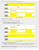
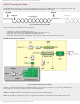
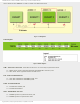
When this first and necessary step is accomplished and START bit is detected, data is transferred to the shift register RSR
through the RX pin. When the STOP bit has been received, the following occurs:
● Data is automatically transferred to the RCREG register (if empty);
● The flag bit RCIF is set and an interrupt, if enabled by the RCIE bit of the PIE1 register, occurs. Similar to
transmitter, the flag bit is cleared by software only, i.e. by reading the RCREG register. Bear in mind that this is a
two character FIFO memory (first-in, first-out) which allows reception of two characters simultaneously;
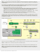
● If the RCREG register is occupied (contains two bytes) and the shift register detects new STOP bit, the overflow bit
OERR will be set. In this case, a new coming data is lost, and the OEER bit must be cleared by software. It is done
by clearing and resetting the CREN bit.
Note: it is not possible to receive new data as far as the OERR bit is set;
● If the STOP bit is zero (0), the FERR bit of the RCSTAregister detecting receive error will be set; and
● To receive 9-bit data it is necessary to set the RX9 bit of the RCSTA register.
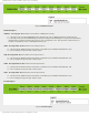
Receive Error Detection
There are two types of errors which the microcontroller can automatically detect. The first one is called Framing error
and occurs when the receiver does not detect the STOP bit at the expected time. Such error is indicated via the FERR bit
of the RCSTA register. If this bit is set, it means that the last received data may be incorrect. It is important to know
several things:
● A Framing error does not generate an interrupt by itself;
● If this bit is set, the last received data has an error;
● A framing error (bit set) does not prevent reception of new data;
● The FERR bit is cleared by reading received data, which means that check must be done before data reading; and
● The FERR bit cannot be cleared by software. If needed, it can be cleared by clearing the SPEN bit of the RCSTA
register. It will simultaneously cause reset of the whole EUSART system.
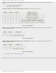
Another type of error is called Overrun Error. The receive FIFO can hold two characters. An overrun error will be
generated if the third character is received. Simply, there is no space for another one byte and an error is unavoidable!
When this happens the OERR bit of the RCSTA register is set. The consequences are the following:
● Data already stored in the FIFO registers (two bytes) can be normally read;
● No additional data will be received until the OERR bit is cleared; and
● This bit is not directly accessed. To clear it, it is necessary to clear the CREN bit of the RCSTA register or to reset
the whole EUSART system by clearing the SPEN bit of the RCSTA register.
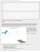
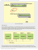
Receiving 9-bit Data
In addition to receiving standard 8-bit data, the EUSART system supports 9-bit data reception. On the transmit side, the
ninth bit is "attached" to the original byte just before the STOP bit. On the receive side, when the RX9 bit of the RCSTA
register is set, the ninth data bit will be automatically written to the RX9D bit of the same register. When this byte is
received, one should take care of how to read its bits- the RX9D data bit must be read before reading the 8 least
significant bits of the RCREG register. Otherwise, the ninth data bit will be automatically cleared.
http://www.mikroe.com/en/books/picmcubook/ch6/ (4 of 27)5/3/2009 11:33:59 AM