
Specifications

mikroElektronika | Free Online Book | PIC Microcontrollers | Chapter 6: Serial Communication Modules
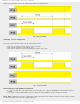
SPEN = 1 - By setting this bit of the RCSTA register, EUSART is enabled and the TX/CK pin is automatically configured as
output. If this bit is simultaneously used for some analog function, it must be disabled by clearing the corresponding bit of
the ANSEL register.
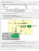
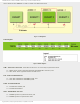
The central part of the EUSART transmitter is the shift register TSR which is not directly accessible by the user. In order to
start transmission, the module must be enabled by setting the TXEN bit of the TXSTA register. Data to be sent should be
written to the TXREG register, which will cause the following sequence of events:
● Byte will be immediately transferred to the shift register TSR;
● TXREG register remains empty, which is indicated by setting flag bit TXIF of the PIR1 register. If the TXIE bit of the
PIE1 register is set, an interrupt will be generated. Besides, the flag is set regardless of whether an interrupt is
enabled or not. Also, it cannot be cleared by software, but by writing new data to the TXREG register;
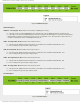
● Control electronics "pushes" data toward the TX pin in rhythm with internal clock: START bit (0) ... data ... STOP bit
(1);
● When the last bit leaves the TSR register, the TRMT bit of the TXSTA regis ter is automatically set; and
● If the TXREG register has received a new character data in the meantime, the whole procedure is repeated
immediately after the STOP bit of the previous character has been transmitted.
Sending 9-bit data is enabled by setting the TX9 bit of the TXSTA register. The TX9D bit of the TXSTA register is the ninth
and Most Significant data bit. When transferring 9-bit data, the TX9D data bit must be written before writing the 8 least
significant bits into the TXREG register. All nine bits of data will be transferred to the TSR shift register immediately after
the TXREG write is complete.
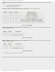
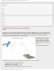
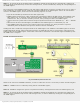
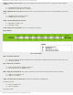
EUSART Asynchronous Receiver
Fig. 6-4 EUSART Asynchronous Receiver
Similar to the activation of EUSART transmitter, in order to enable the receiver it is necessary to define the following bits:
CREN = 1 - EUSART receiver is enabled by setting this bit of the RCSTA register;
SYNC = 0 - EUSART is configured to operate in asynchronous mode by clearing this bit stored in the TXSTA register; and
SPEN = 1 - By setting this bit of the RCSTA register, EUSART is enabled and the RX/DT pin is automatically configured as
input. If this bit is simultaneously used for some analog function, it must be disabled by clearing the corresponding bit of
the ANSEL register.
http://www.mikroe.com/en/books/picmcubook/ch6/ (3 of 27)5/3/2009 11:33:59 AM