
Specifications

mikroElektronika | Free Online Book | PIC Microcontrollers | Chapter 5: CCP Modules
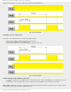
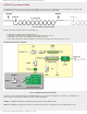
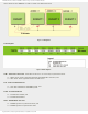
Figure below shows the state of the P1A-P1D pins during one full PWM cycle.
Fig. 5-16 Forward Mode
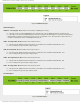
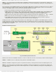
Full Bridge - Reverse Configuration
The same occurs in Reverse mode, except of the pins functions:
● Logic one (1) appears on the P1C pin (pin is active-high);
● Pulse sequence appears on the P1B pin; and
● Logic zero (0) appears on the P1A and P1D pins (pins are active-low).
Fig. 5-17 Reverse Mode
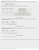
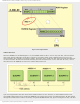
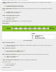
PWM1CON Register STRC PWM Restart Enable bit
● 1 - Upon auto-shutdown, the PWM module is automatically reset, while the ECCPASE bit of the ECCPAS register is
cleared.
● 0 - In order to restart PWM module upon auto-shutdown, the ECCPASE bit must be cleared in software.
PDC6 - PDC0 - PWM Delay Count bits. 7-digit binary number determines the number of instruction cycles (4*Tosc) added
as time delay during the activation of PWM output pins.
http://www.mikroe.com/en/books/picmcubook/ch5/ (13 of 15)5/3/2009 11:33:21 AM