
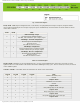
Specifications

mikroElektronika | Free Online Book | PIC Microcontrollers | Chapter 5: CCP Modules
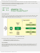
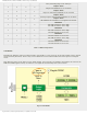
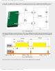
In this mode, the PWM signal is output on the P1A pin, while at the same time the complementary PWM signal is output on
the P1B pin. Such pulses activate MOSFET drivers in Half-Bridge mode which enable/disable current flow through device.
Fig. 5-12 Half-Bridge Mode
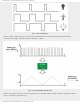
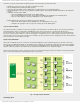
In relation to this circuit, it is very dangerous to switch on both MOSFET drivers simultaneously. The short circuit caused in
that moment will be fatal. In order to avoid that, it is necessary to provide a short delay between switching drivers on and
off. This delay is marked as "td" in figure 5-13 below. The problem is solved by using the PDC0-PDC6 bits of the PWM1CON
register.
Fig. 5-13 Half Bridge Mode
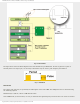
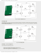
As shown in figure 5-14, the same mode can be used to activate MOSFET drivers in Full Bridge:
http://www.mikroe.com/en/books/picmcubook/ch5/ (11 of 15)5/3/2009 11:33:21 AM