
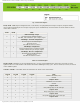
Specifications

mikroElektronika | Free Online Book | PIC Microcontrollers | Chapter 5: CCP Modules
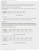
In order to setup the CCP module for PWM operation, the following steps should be taken:
● Disable the CCP1 output pin. It should be configured as input;
● Set the PWM period by loading the PR2 register;
● Configure the CCP module for the PWM mode by combining bits of the CCP1CON register;
● Set the PWM signal’s duty cycle by loading the CCPR1L register and using bits DC1B1 and DC1B0 of the CCP1CON
register;
● Configure and start timer TMR2:
❍ Clear the TMR2IF interrupt flag bit of the PIR1 register;
❍ Set the timer TMR2 prescale value by loading bits T2CKPS1 and T2CKPS0 of the T2CON register;
❍ Start the timer TMR2 by setting the TMR2ON bit of the T2CON register;
● Enable PWM output pins after one PWM cycle has been finished:
❍ Wait for the timer TMR2 overflow (TMR2IF bit of the PIR1register is set); and
❍ Configure the appropriate pin as output by clearing bit of the TRIS register.
CCP1 in Enhanced Mode
The enhanced mode is available on CCP1 only. Basically, this module does not differ from the one previously described
and enhancement refers to transmission of PWM signal to the output pins. Why is it so important? Because the
microcontrollers are more frequently used in control systems for electric motors. These devices are not described here,
but if you ever have had a chance to work on development of similar devices, you will recognize elements which, until
quite recently, have been used as external ones. Normally, all these elements are now integrated into the microcontroller
and can operate in several different modes.
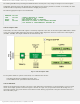
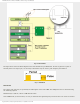
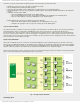
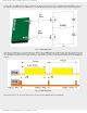
Single Output PWM Mode
This mode is enabled only in the event that the P1M1 and P1M0 bits of the CCP1CON register are cleared. In this case,
there is only one PWM signal which can be simultaneously available on a maximum of four different output pins. Besides,
the PWM signal may appear in basic or inverted waveform. Signal distribution is determined by the bits of the PSTRCON
register, while it's polarity is determined by the CCP1M1 and CCP1M0 bits of the CCP1CON register.
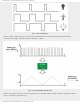
When an inverted output is in use, the pins are low-active and pulses having the same waveform are always generated in
pairs: on the P1A and P1C pins and P1B and P1D pins, respectively.
Fig. 5-11 Single Output PWM Mode
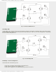
Half-Bridge Mode
http://www.mikroe.com/en/books/picmcubook/ch5/ (10 of 15)5/3/2009 11:33:21 AM