
Specifications

mikroElektronika | Free Online Book | PIC Microcontrollers | Chapter 5: CCP Modules
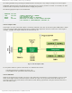
Similar to the pervious module, this circuit is under control of the bits of the control register. This time, it is the CCP2CON
register.
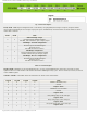
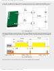
CCP2CON Register
Fig. 5-10 CCP2CON Register
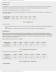
DC2B1, DC2B0 - PWM Duty Cycle Least Significant bits - are only used in PWM mode representing two least significant bits
of a 10-bit number. This number determines PWM signal’s duty cycle. The rest of bits (8 in total) are stored in the CCPR2L
register.
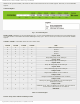
CCP2M3 - CCP2M0 - CCP2 Mode Select bits select CCP2 mode.
CCP2M3 CCP2M2 CCP2M1 CCP2M0 Mode
0 0 0 0 Module is disabled (reset)
0 0 0 1 Unused
0 0 1 0 Unused
0 0 1 1 Unused
0 1 0 0
Capture mode
Every falling edge on the CCP2 pin
0 1 0 1
Capture mode
Every raising edge on the CCP2 pin
0 1 1 0
Capture mode
Every 4th rising edge on the CCP2 pin
0 1 1 1
Capture mode
Every 16th rising edge on the CCP2 pin
1 0 0 0
Compare mode
Output and CCP2IF bit are set on match
1 0 0 1
Compare mode
Output is cleared and CCP2IF bit is set on match
1 0 1 0
Compare mode
Interrupt is generated, CCP2IF bit is set and CCP2 pin is
unaffected on match
1 0 1 1
Compare mode
CCP2IF bit is set, Timer 1 registers are cleared, A/D conversion is
started if the A/D converter is on on match
1 1 x x
PWM mode
Table 5-6 CCP2CON Register
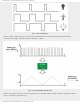
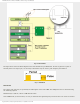
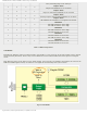
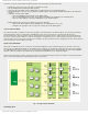
In short: Setup CCP1 module for PWM operation
http://www.mikroe.com/en/books/picmcubook/ch5/ (9 of 15)5/3/2009 11:33:21 AM