
Specifications

mikroElektronika | Free Online Book | PIC Microcontrollers | Chapter 5: CCP Modules
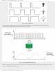
Every 16th rising edge on the CCP1 pin
1 0 0 0
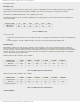
Compare mode
Output and CCP1IF bit are set on match
1 0 0 1
Compare mode
Output is cleared and CCP1IF bit is set on match
1 0 1 0
Compare mode
Interrupt request arrives and bit CCP1IF is set on match
1 0 1 1
Compare mode
Bit CCP1IF is set and timers 1 or 2 registers are cleared
1 1 0 0
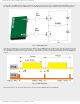
PWM mode
Pins P1A and P1C are active-high
Pins P1B and P1D are active-high
1 1 0 1
PWM mode
Pins P1A and P1C are active-high
Pins P1B and P1D are active-low
1 1 1 0
PWM mode
Pins P1A and P1C are active-low
Pins P1B and P1D are active-high
1 1 1 1
PWM mode
Pins P1A and P1C are active-low
Pins P1B and P1D are active-low
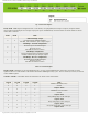
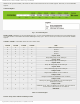
Table 5-5 Modes of Operations
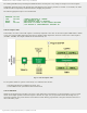
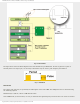
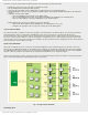
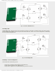
CCP2 Module
Excluding the different names of registers and bits, this module is a very good copy of the CCP1 module setup in normal
mode (previously discussed). There is only one true difference between their modes when CCP2 operates in Compare
mode.
That difference refers to the timer T1 reset signal. Namely, if A/D converter is enabled at the moment the values of the
TMR1 and CCPR2 registers match, the timer T1 reset signal will automatically start A/D conversion.
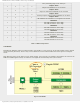
Fig. 5-9 CCP2 Module
http://www.mikroe.com/en/books/picmcubook/ch5/ (8 of 15)5/3/2009 11:33:21 AM