
Specifications

mikroElektronika | Free Online Book | PIC Microcontrollers | Chapter 5: CCP Modules
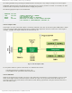
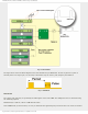
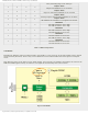
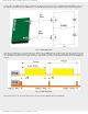
Fig. 5-6 PWM module
The figure above shows the block diagram of the CCP1 module setup in PWM mode. In order to generate a pulse of
arbitrary form on its output pin, it is necessary to determine only two values- pulse frequency and duration.
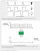
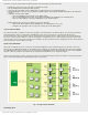
Fig.5-7 PWM Mode
PWM Period
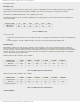
The output pulse period (T) is specified by the PR2 register of the timer TMR2. The PWM period can be calculated using
the following equation:
PWM Period(T) = (PR2 +1) * 4Tosc * TMR2 Prescale Value
If the PWM Period (T) is known then, it is easy to determine the signal frequency F because these two values are related
http://www.mikroe.com/en/books/picmcubook/ch5/ (5 of 15)5/3/2009 11:33:21 AM