
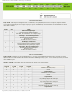
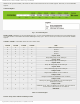
Specifications

mikroElektronika | Free Online Book | PIC Microcontrollers | Chapter 5: CCP Modules
bit enabling CCP1IE interrupt and flag bit CCP1IF should be cleared prior to any change occuring in the control register.
Undesirable interrupt may be also generated by switching from one capture prescaler to another. To avoid this, the CCP1
module should be temporarily switched off before changing the prescaler.
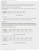
The following program sequence is recommended:
BANKESEL CCP1CON
CLRF CCP1CON ;CONTROL REGISTER IS CLEARED
;CCP1 MODULE IS OFF
MOVLW XX ;NEW PRESCALER MODE IS SELECTED
MOVWF CCP1CON ;NEW VALUE IS LOADED TO THE CONTROL REGISTER
;CCP1 MODULE IS SIMULTANEOUSLY SWITCHED ON
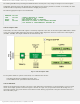
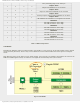
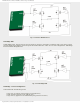
CCP1 in Compare mode
In this mode, the value in the CCP1 register is constantly compared to the value in the timer register TMR1. When a match
occurs, the output pin RC2/CCP1 logic state may be changed, which depends on the state of bits in the control register
(CCP1M3 - CCP1M0). The flag-bit CCP1IF will be simultaneously set.
Fig. 5-3 CCP1 in Compare mode
To setup CCP1 module to operate in this mode, two conditions must be met:
● Pin RC2/CCP1 must be configured as output; and
● Timer TMR1 must be synchronized with internal clock.
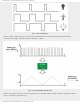
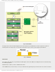
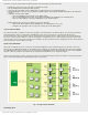
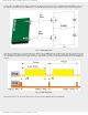
CCP1 in PWM mode
Signals of varying frequency and duty cycle have a wide application in automation. A typical example is a power control
circuit whose simple operation is shown in figure 5-4 below. If a logic zero (0) represents switch-off and logic one (1)
represents switchon, the power that the load consumes will be directly proportional to the pulse duration. This ratio is
often called Duty Cycle.
http://www.mikroe.com/en/books/picmcubook/ch5/ (3 of 15)5/3/2009 11:33:21 AM