
Specifications

mikroElektronika | Free Online Book | PIC Microcontrollers | Chapter 5: CCP Modules
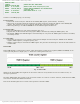
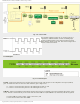
Fig. 5-1 CCP1 Module
In Compare mode, if enabled by software, the timer TMR1 reset may occur on match. Besides, the CCP1 module can
generate PWM signals of varying frequency and duty cycle.
Bits of the CCP1CON register controls the CCP1 module.
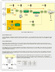
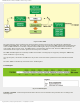
CCP1 in Capture mode
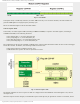
In this mode, the timer register TMR1 (consisting of TMR1H and TMR1L) is copied to the CCP1 register (consisting of
CCPR1H and CCPR1L) in the following situations:
● Every falling edge (1 » 0) on the RC2/CCP1 pin;
● Every rising edge (0 » 1) on the RC2/CCP1 pin;
● Every 4th rising edge (0 » 1) on the RC2/CCP1 pin; and
● Every 16th rising edge (0 » 1) on the RC2/CCP1 pin.
The combination of the four bits (CCP1M3 - CCP1M0) of the control register determines which of these events will trigger
16-bit data transfer. In addition, the following conditions must be met:
● RC2/CCP1 pin must be configured as input; and
● TMR1 module must operate as timer or synchronous counter.
Fig. 5-2 CCP1 in Capture mode
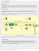
The flag bit CCP1IF is set when a capture is made. If it happens and if the CCP1IE bit of the PIE register is set, then an
interrupt occurs.
When the Capture mode is changed, an undesirable capture interrupts may be generated. In order to avoid that, both a
http://www.mikroe.com/en/books/picmcubook/ch5/ (2 of 15)5/3/2009 11:33:21 AM