
Specifications

mikroElektronika | Free Online Book | PIC Microcontrollers | Chapter 4: Timers
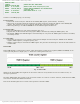
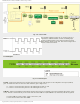
T1CKPS1, T1CKPS0 - Timer1 Input Clock Prescale Select bits determine the rate of the prescaler assigned to the timer
TMR1.
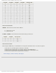
T1CKPS1 T1CKPS0 Prescaler Rate
0 0 1:1
0 1 1:2
1 0 1:4
1 1 1:8
Table 4-2 Prescaler Rate
T1OSCEN - LP Oscillator Enable Control bit
● 1 - LP oscillator is enabled for timer TMR1 clock (oscillator with low power consumption and frequency 32.768 kHz);
and
● 0 - LP oscillator is off.
T1SYNC - Timer1 External Clock Input Synchronization Control bit enables synchronization of the LP oscillator input or
T1CKI pin input with the microcontroller internal clock. When counting pulses from the local clock source (bit TMR1CS =
0), this bit is ignored.
● 1 - Do not synchronize external clock input; and
● 0 - Synchronize external clock input.
TMR1CS - Timer TMR1 Clock Source Select bit
● 1 - Counts pulses on the T1CKI pin (on the rising edge 0-1); and
● 0 - Counts pulses of the internal clock of microcontroller.
TMR1ON - Timer1 On bit
● 1 - Enables Timer TMR1; and
● 0 - Stops Timer TMR1.
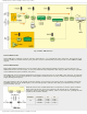
In order to use the timer TMR1 properly, it is necessary to perform the following:
● Since it is not possible to turn off the prescaler, its rate should be adjusted by using bits T1CKPS1 and T1CKPS0 of
the register T1CON (Refer to table 4-2);
● The mode should be selected by the TMR1CS bit of the same register (TMR1CS: 0= the clock source is quartz
oscillator, 1= the clock source is supplied externally);
● By setting the T1OSCEN bit of the same register, the timer TMR1 is turned on and the TMR1H and TMR1L registers
are incremented on every clock input. Counting stops by clearing this bit;
● The prescaler is cleared by clearing or writing the counter registers; and
● By filling both timer registers, the flag TMR1IF is set and counting starts from zero.
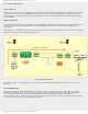
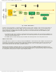
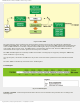
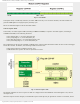
Timer TMR2
Timer TMR2 module is an 8-bit timer which operates in a very specific way.
http://www.mikroe.com/en/books/picmcubook/ch4/ (10 of 12)5/3/2009 11:32:57 AM