
Specifications

mikroElektronika | Free Online Book | PIC Microcontrollers | Chapter 4: Timers
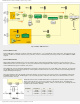
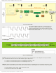
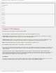
Fig. 4-11 Counter Mode
This counter registers a logic one (1) on input pins. It is
important to understand that at least one falling edge
must be registered prior to the first increment on rising
edge. Refer to figure on the left. The arrows in figure 4-11
denote counter increments.
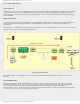
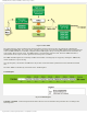
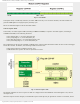
T1CON Register
Fig. 4-12 T1CON Register
T1GINV - Timer1 Gate Invert bit acts as logic state inverter on the T1G pin gate or the comparator C2 output (C2OUT)
gate. It enables the timer to mea sure time whilst the gate is high or low.
● 1 - Timer 1 counts when the pin T1G or bit C2OUT gate is high (1); and
● 0 - Timer 1 counts when the pin T1G or bit C2OUT gate is low (0).
TMR1GE - Timer1 Gate Enable bit determines whether the pin T1G or comparator C2 output (C2OUT) gate will be active
or not. This bit is functional only in the event that the timer TMR1 is on (bit TMR1ON = 1). Otherwise, this bit is ignored.
● 1 Timer TMR1 is on only if timer 1 gate is not active; and
● 0 Gate does not affect the timer TMR1.
http://www.mikroe.com/en/books/picmcubook/ch4/ (9 of 12)5/3/2009 11:32:57 AM