
Specifications

mikroElektronika | Free Online Book | PIC Microcontrollers | Chapter 4: Timers
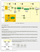
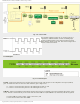
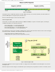
Fig. 4-9 Timer TMR1 Oscillator
In order to solve this problem, a completely independent Low Power quartz oscillator, able to operate in sleep mode, is
built into the PIC16F887 microcontroller. Simply, what previously has been a separate circuit, it is now built into the
microcontroller and assigned to the timer TMR1. The oscillator is enabled by setting the T1OSCEN bit of the T1CON
register. After that, the TMR1CS bit of the same register then is used to determine that the timer TMR1 uses pulse
sequences from that oscillator.
● The signal from this quartz oscillator is synchronized with the microcontroller clock by clearing the T1SYNC bit. In
that case, the timer cannot operate in sleep mode. You wonder why? Because the circuit for synchronization uses
the clock of microcontroller!; and
● The TMR1 register overflow interrupt may be enabled. Such interrupts will occur in sleep mode as well.
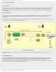
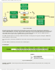
TMR1 in counter mode
Timer TMR1 starts to operate as a counter by setting the TMR1CS bit. It means that the timer TMR1 is incremented on the
rising edge of the external clock input T1CKI. If control bit T1SYNC of the T1CON register is cleared, the external clock
inputs will be synchronized on their way to the TMR1 register. In other words, the timer TMR1 is synchronized to the
microcontroller system clock and called a synchronous counter.
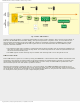
When the microcontroller ,operating in this way, is set in sleep mode, the TMR1H and TMR1L timer registers are not
incremented even though clock pulses appear on the input pins. Simply, since the microcontroller system clock does not
run in this mode, there are no clock inputs to use for synchronization. However, the prescaler will continue to run if there
are clock pulses on the pins since it is just a simple frequency divider.
http://www.mikroe.com/en/books/picmcubook/ch4/ (8 of 12)5/3/2009 11:32:57 AM