
Specifications

mikroElektronika | Free Online Book | PIC Microcontrollers | Chapter 4: Timers
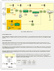
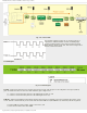
Fig. 4-7 Timer TMR1 Oscillator
Timer TMR1 Gate
Timer 1 gate source is software configurable to be the T1G pin or the output of comparator C2. This gate allows the timer
to directly time external events using the logic state on the T1G pin or analog events using the comparator C2 output.
Refer to figure 4-7 above. In order to time a signals duration it is sufficient to enable such gate and count pulses having
passed through it.
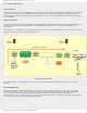
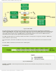
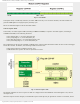
TMR1 in timer mode
In order to select this mode, it is necessary to clear the TMR1CS bit. After this, the 16-bit register will be incremented on
every pulse coming from the internal oscillator. If the 4MHz quartz crystal is in use, it will be incremented every
microsecond.
In this mode, the T1SYNC bit does not affect the timer because it counts internal clock pulses. Since the whole electronics
uses these pulses, there is no need for synchronization.
Fig. 4-8 TMR1 in timer mode
The microcontroller’s clock oscillator does not run during sleep mode so the timer register overflow cannot cause any
interrupt.
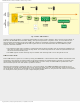
Timer TMR1 Oscillator
The power consumption of the microcontroller is reduced to the lowest level in Sleep mode. The point is to stop the
oscillator. Anyway, it is easy to set the timer in this mode- by writing a SLEEP instruction to the program. A problem
occurs when it is necessary to wake up the microcontroller because only an interrupt can do that. Since the
microcontroller “sleeps”, an interrupt must be triggered by external electronics. It can all get incredibly complicated if it
is necessary the ‘wake up’ occurs at regular time intervals...
http://www.mikroe.com/en/books/picmcubook/ch4/ (7 of 12)5/3/2009 11:32:57 AM